ATEVK1104 Atmel, ATEVK1104 Datasheet - Page 29
ATEVK1104
Manufacturer Part Number
ATEVK1104
Description
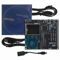
KIT DEV/EVAL FOR AVR32 AT32UC3A
Manufacturer
Atmel
Series
AVR®32r
Type
MCUr
Datasheets
1.ATAVRONE-PROBECBL.pdf
(16 pages)
2.ATEVK1104.pdf
(826 pages)
3.ATEVK1104.pdf
(90 pages)
4.ATEVK1104.pdf
(6 pages)
5.ATEVK1104.pdf
(12 pages)
Specifications of ATEVK1104
Contents
Evaluation Board, Software and Documentation
Processor To Be Evaluated
AT32UC3A3
Data Bus Width
32 bit
Interface Type
USB, SPI, USART
Silicon Manufacturer
Atmel
Core Architecture
AVR
Core Sub-architecture
AVR UC3
Silicon Core Number
AT32UC3A3256
Silicon Family Name
AVR
Kit Contents
Board CD Docs
Rohs Compliant
Yes
For Use With/related Products
AT32UC3A3
Lead Free Status / RoHS Status
Lead free / RoHS Compliant
Available stocks
Company
Part Number
Manufacturer
Quantity
Price
Company:

Part Number:
ATEVK1104
Manufacturer:
Atmel
Quantity:
135


9.4
9.4.1
32058J–AVR32–04/11
Exceptions and Interrupts
System stack issues
Table 9-3.
AVR32UC incorporates a powerful exception handling scheme. The different exception sources,
like Illegal Op-code and external interrupt requests, have different priority levels, ensuring a well-
defined behavior when multiple exceptions are received simultaneously. Additionally, pending
exceptions of a higher priority class may preempt handling of ongoing exceptions of a lower pri-
ority class.
When an event occurs, the execution of the instruction stream is halted, and execution control is
passed to an event handler at an address specified in
dlers are placed sequentially in the code space starting at the address specified by EVBA, with
four bytes between each handler. This gives ample space for a jump instruction to be placed
there, jumping to the event routine itself. A few critical handlers have larger spacing between
them, allowing the entire event routine to be placed directly at the address specified by the
EVBA-relative offset generated by hardware. All external interrupt sources have autovectored
interrupt service routine (ISR) addresses. This allows the interrupt controller to directly specify
the ISR address as an address relative to EVBA. The autovector offset has 14 address bits, giv-
ing an offset of maximum 16384 bytes. The target address of the event handler is calculated as
(EVBA | event_handler_offset), not (EVBA + event_handler_offset), so EVBA and exception
code segments must be set up appropriately. The same mechanisms are used to service all dif-
ferent types of events, including external interrupt requests, yielding a uniform event handling
scheme.
An interrupt controller does the priority handling of the external interrupts and provides the
autovector offset to the CPU.
Event handling in AVR32 UC uses the system stack pointed to by the system stack pointer,
SP_SYS, for pushing and popping R8-R12, LR, status register and return address. Since event
code may be timing-critical, SP_SYS should point to memory addresses in the IRAM section,
since the timing of accesses to this memory section is both fast and deterministic.
Reg #
92
93
94
95
96
97
98
99
100
101
102
103-191
192-255
Address
368
372
376
380
384
388
392
396
400
404
408
412-764
768-1020
System Registers (Continued)
Name
MPUPSR4
MPUPSR5
MPUPSR6
MPUPSR7
MPUCRA
MPUCRB
MPUBRA
MPUBRB
MPUAPRA
MPUAPRB
MPUCR
Reserved
IMPL
Function
MPU Privilege Select Register region 4
MPU Privilege Select Register region 5
MPU Privilege Select Register region 6
MPU Privilege Select Register region 7
Unused in this version of AVR32UC
Unused in this version of AVR32UC
Unused in this version of AVR32UC
Unused in this version of AVR32UC
MPU Access Permission Register A
MPU Access Permission Register B
MPU Control Register
Reserved for future use
IMPLEMENTATION DEFINED
Table 9-4 on page
AT32UC3A
32. Most of the han-
29
Related parts for ATEVK1104
Image
Part Number
Description
Manufacturer
Datasheet
Request
R

Part Number:
Description:
DEV KIT FOR AVR/AVR32
Manufacturer:
Atmel
Datasheet:

Part Number:
Description:
INTERVAL AND WIPE/WASH WIPER CONTROL IC WITH DELAY
Manufacturer:
ATMEL Corporation
Datasheet:
Part Number:
Description:
Low-Voltage Voice-Switched IC for Hands-Free Operation
Manufacturer:
ATMEL Corporation
Datasheet:
Part Number:
Description:
MONOLITHIC INTEGRATED FEATUREPHONE CIRCUIT
Manufacturer:
ATMEL Corporation
Datasheet:
Part Number:
Description:
AM-FM Receiver IC U4255BM-M
Manufacturer:
ATMEL Corporation
Datasheet:
Part Number:
Description:
Monolithic Integrated Feature Phone Circuit
Manufacturer:
ATMEL Corporation
Datasheet:
Part Number:
Description:
Multistandard Video-IF and Quasi Parallel Sound Processing
Manufacturer:
ATMEL Corporation
Datasheet:
Part Number:
Description:
High-performance EE PLD
Manufacturer:
ATMEL Corporation
Datasheet:
Part Number:
Description:
8-bit Flash Microcontroller
Manufacturer:
ATMEL Corporation
Datasheet:
Part Number:
Description:
2-Wire Serial EEPROM
Manufacturer:
ATMEL Corporation
Datasheet: