ATEVK1104 Atmel, ATEVK1104 Datasheet - Page 678
ATEVK1104
Manufacturer Part Number
ATEVK1104
Description
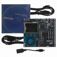
KIT DEV/EVAL FOR AVR32 AT32UC3A
Manufacturer
Atmel
Series
AVR®32r
Type
MCUr
Datasheets
1.ATAVRONE-PROBECBL.pdf
(16 pages)
2.ATEVK1104.pdf
(826 pages)
3.ATEVK1104.pdf
(90 pages)
4.ATEVK1104.pdf
(6 pages)
5.ATEVK1104.pdf
(12 pages)
Specifications of ATEVK1104
Contents
Evaluation Board, Software and Documentation
Processor To Be Evaluated
AT32UC3A3
Data Bus Width
32 bit
Interface Type
USB, SPI, USART
Silicon Manufacturer
Atmel
Core Architecture
AVR
Core Sub-architecture
AVR UC3
Silicon Core Number
AT32UC3A3256
Silicon Family Name
AVR
Kit Contents
Board CD Docs
Rohs Compliant
Yes
For Use With/related Products
AT32UC3A3
Lead Free Status / RoHS Status
Lead free / RoHS Compliant
Available stocks
Company
Part Number
Manufacturer
Quantity
Price
Company:

Part Number:
ATEVK1104
Manufacturer:
Atmel
Quantity:
135


32058J–AVR32–04/11
• the waveform duty cycle. This channel parameter is defined in the CDTY field of the CDTYx
• the waveform polarity. At the beginning of the period, the signal can be at high or low level.
• the waveform alignment. The output waveform can be left or center aligned. Center aligned
- If the waveform is left aligned, then the output waveform period depends on the counter
source clock and can be calculated:
By using the Master Clock (MCK) divided by an X given prescaler value
(with X being 1, 2, 4, 8, 16, 32, 64, 128, 256, 512, or 1024), the resulting period formula will be:
By using a Master Clock divided by one of both DIVA or DIVB divider, the formula becomes,
respectively:
If the waveform is center aligned then the output waveform period depends on the counter
source clock and can be calculated:
By using the Master Clock (MCK) divided by an X given prescaler value
(with X being 1, 2, 4, 8, 16, 32, 64, 128, 256, 512, or 1024). The resulting period formula will
be:
By using a Master Clock divided by one of both DIVA or DIVB divider, the formula becomes,
respectively:
register.
If the waveform is left aligned then:
If the waveform is center aligned, then:
This property is defined in the CPOL field of the CMRx register. By default the signal starts by
a low level.
waveforms can be used to generate non overlapped waveforms. This property is defined in the
CALG field of the CMRx register. The default mode is left aligned.
(
------------------------------ -
(
----------------------------------------- -
(
---------------------------------------- - -
(
--------------------------------------------------- - -
X CPRD
CRPD
2
2
duty cycle
×
×
×
duty cycle
MCK
X CPRD
CPRD DIVA
MCK
MCK
×
MCK
×
DIVA
)
×
=
)
)
=
or
(
------------------------------------------------------------------------------------------------------- - -
period 1 fchannel_x_clock
(
---------------------------------------------------------------------------------------------------------------------- - -
)
(
period 2 ⁄
(
--------------------------------------------- -
or
CRPD
(
--------------------------------------------------- - -
2 CPRD
–
MCK
×
×
DIVAB
⁄
) 1 fchannel_x_clock
MCK
–
×
period
⁄
(
)
DIVB
period 2 ⁄
)
)
×
CDTY
×
CDTY
)
) )
AT32UC3A
678
Related parts for ATEVK1104
Image
Part Number
Description
Manufacturer
Datasheet
Request
R

Part Number:
Description:
DEV KIT FOR AVR/AVR32
Manufacturer:
Atmel
Datasheet:

Part Number:
Description:
INTERVAL AND WIPE/WASH WIPER CONTROL IC WITH DELAY
Manufacturer:
ATMEL Corporation
Datasheet:
Part Number:
Description:
Low-Voltage Voice-Switched IC for Hands-Free Operation
Manufacturer:
ATMEL Corporation
Datasheet:
Part Number:
Description:
MONOLITHIC INTEGRATED FEATUREPHONE CIRCUIT
Manufacturer:
ATMEL Corporation
Datasheet:
Part Number:
Description:
AM-FM Receiver IC U4255BM-M
Manufacturer:
ATMEL Corporation
Datasheet:
Part Number:
Description:
Monolithic Integrated Feature Phone Circuit
Manufacturer:
ATMEL Corporation
Datasheet:
Part Number:
Description:
Multistandard Video-IF and Quasi Parallel Sound Processing
Manufacturer:
ATMEL Corporation
Datasheet:
Part Number:
Description:
High-performance EE PLD
Manufacturer:
ATMEL Corporation
Datasheet:
Part Number:
Description:
8-bit Flash Microcontroller
Manufacturer:
ATMEL Corporation
Datasheet:
Part Number:
Description:
2-Wire Serial EEPROM
Manufacturer:
ATMEL Corporation
Datasheet: