IPTR-DSPBUILDER Altera, IPTR-DSPBUILDER Datasheet - Page 63

IPTR-DSPBUILDER
Manufacturer Part Number
IPTR-DSPBUILDER
Description
DSP BUILDER SOFTWARE
Manufacturer
Altera
Type
DSPr
Specifications of IPTR-DSPBUILDER
Function
DSP Builder
License
Renewal License
Software Application
IP CORE, DSP BUILDER
Core Architecture
FPGA
Core Sub-architecture
Arria, Cyclone, Stratix
Supported Families
Arria GX, Arria II GX, Cyclone, Stratix
Rohs Compliant
NA
Lead Free Status / RoHS Status
Not applicable / Not applicable
- Current page: 63 of 422
- Download datasheet (6Mb)
Chapter 3: Design Rules and Procedures
Signal Compiler and TestBench Blocks
Signal Compiler and TestBench Blocks
Design Flows for Synthesis, Compilation and Simulation
© June 2010 Altera Corporation
f
f
The Signal Compiler block uses Quartus II synthesis to convert a Simulink design
into synthesizable VHDL including generation of a VHDL testbench and other
supporting files for simulation and synthesis.
Signal Compiler assumes that your design complies with the Simulink rules and
that any variables and inherited variables propagate through the whole design.
You should always run a simulation in Simulink before running Signal Compiler.
The simulation updates all variables in your design (including workspace variables
and inherited parameters), sets up certain blocks (such as the memory blocks, and
inputs from and outputs to workspace blocks), and also traps any design errors that
do not comply with Simulink rules.
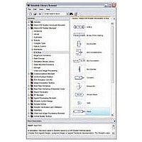
The Input and Output blocks map to input and output ports in VHDL and mark the
edge of the generated system. Typically, you connect these blocks to the Simulink
simulation blocks for your testbench. An Output block should not connect to another
Altera block. If you connect more Altera blocks (that map to HDL), empty ports are
created and the HDL does not compile for synthesis.
For more information about the Input and Output blocks, refer to the IO & Bus
Library chapter of the
You can use the Signal Compiler and Testbench blocks to control your design
flow for synthesis, compilation, and simulation. DSP Builder supports the following
flows:
■
■
■
For an example that uses the Signal Compiler blocker, refer to
“Getting
For information about the parameters for the Signal Compiler and TestBench
blocks, refer to the AltLab Library chapter of the
Automatic flow—allows you to control the entire design process in the MATLAB
or Simulink environment with the Signal Compiler block. With this flow, your
design compiles inside a temporary Quartus II project. The results of the synthesis
and compilation display in the Signal Compiler Messages box. You can also use
the automatic flow to download your design into supported development boards.
Manual flow—you can also add the .mdl file to an existing Quartus II project
using the <model name>_add.tcl script. This script is generated whenever the
Signal Compiler or TestBench block is run. You can use the script to add the
.mdl file and any imported HDL to your project. You can then instantiate your
design in HDL.
Simulation flow—if the ModelSim executable (vsim.exe) is on your path, you can
use the TestBench block to compile your design for ModelSim simulation. You
can then automatically compare the Simulink and ModelSim simulation results.
Started”.
DSP Builder Reference
Preliminary
Manual.
DSP Builder Reference
DSP Builder Standard Blockset User Guide
page 2–14
Manual.
of the
3–19
Related parts for IPTR-DSPBUILDER
Image
Part Number
Description
Manufacturer
Datasheet
Request
R

Part Number:
Description:
CYCLONE II STARTER KIT EP2C20N
Manufacturer:
Altera
Datasheet:

Part Number:
Description:
CPLD, EP610 Family, ECMOS Process, 300 Gates, 16 Macro Cells, 16 Reg., 16 User I/Os, 5V Supply, 35 Speed Grade, 24DIP
Manufacturer:
Altera Corporation
Datasheet:

Part Number:
Description:
CPLD, EP610 Family, ECMOS Process, 300 Gates, 16 Macro Cells, 16 Reg., 16 User I/Os, 5V Supply, 15 Speed Grade, 24DIP
Manufacturer:
Altera Corporation
Datasheet:

Part Number:
Description:
Manufacturer:
Altera Corporation
Datasheet:

Part Number:
Description:
CPLD, EP610 Family, ECMOS Process, 300 Gates, 16 Macro Cells, 16 Reg., 16 User I/Os, 5V Supply, 30 Speed Grade, 24DIP
Manufacturer:
Altera Corporation
Datasheet:

Part Number:
Description:
High-performance, low-power erasable programmable logic devices with 8 macrocells, 10ns
Manufacturer:
Altera Corporation
Datasheet:

Part Number:
Description:
High-performance, low-power erasable programmable logic devices with 8 macrocells, 7ns
Manufacturer:
Altera Corporation
Datasheet:

Part Number:
Description:
Classic EPLD
Manufacturer:
Altera Corporation
Datasheet:

Part Number:
Description:
High-performance, low-power erasable programmable logic devices with 8 macrocells, 10ns
Manufacturer:
Altera Corporation
Datasheet:

Part Number:
Description:
Manufacturer:
Altera Corporation
Datasheet:

Part Number:
Description:
Manufacturer:
Altera Corporation
Datasheet:

Part Number:
Description:
Manufacturer:
Altera Corporation
Datasheet:

Part Number:
Description:
CPLD, EP610 Family, ECMOS Process, 300 Gates, 16 Macro Cells, 16 Reg., 16 User I/Os, 5V Supply, 25 Speed Grade, 24DIP
Manufacturer:
Altera Corporation
Datasheet:


