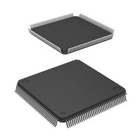
D12674RVFQ33D Renesas Electronics America, D12674RVFQ33D Datasheet - Page 811

D12674RVFQ33D
Manufacturer Part Number
D12674RVFQ33D
Description
MCU 3V 0K I-TEMP 144-QFP
Manufacturer
Renesas Electronics America
Series
H8® H8S/2600r
Datasheet
1.D12674RVFQ33V.pdf
(981 pages)
Specifications of D12674RVFQ33D
Core Processor
H8S/2600
Core Size
16-Bit
Speed
33MHz
Connectivity
IrDA, SCI
Peripherals
DMA, POR, PWM, WDT
Number Of I /o
103
Program Memory Type
ROMless
Ram Size
32K x 8
Voltage - Supply (vcc/vdd)
3 V ~ 3.6 V
Data Converters
A/D 12x10b; D/A 4x8b
Oscillator Type
Internal
Operating Temperature
-40°C ~ 85°C
Package / Case
144-LQFP
Lead Free Status / RoHS Status
Contains lead / RoHS non-compliant
Eeprom Size
-
Program Memory Size
-
Other names
HD6412674RVFQ33D
HD6412674RVFQ33D
HD6412674RVFQ33D
Available stocks
Company
Part Number
Manufacturer
Quantity
Price
Company:
Part Number:
D12674RVFQ33DV
Manufacturer:
Renesas Electronics America
Quantity:
10 000
- Current page: 811 of 981
- Download datasheet (6Mb)
16.7
16.7.1
Operation of the A/D converter can be disabled or enabled using the module stop control register.
The initial setting is for operation of the A/D converter to be halted. Register access is enabled by
clearing module stop mode. For details, refer to section 22, Power-Down Modes.
16.7.2
This LSI’s analog input is designed so that conversion precision is guaranteed for an input signal
for which the signal source impedance is 10 k or less. This specification is provided to enable
the A/D converter’s sample-and-hold circuit input capacitance to be charged within the sampling
time; if the sensor output impedance exceeds 10 k , charging may be insufficient and it may not
be possible to guarantee the A/D conversion accuracy. However, if a large capacitance is provided
externally for conversion in single mode, the input load will essentially comprise only the internal
input resistance of 10 k , and the signal source impedance is ignored. However, since a low-pass
filter effect is obtained in this case, it may not be possible to follow an analog signal with a large
differential coefficient (e.g., 5 mV/ s or greater) (see figure 16.6). When converting a high-speed
analog signal or conversion in scan mode, a low-impedance buffer should be inserted.
Sensor input
Usage Notes
Module Stop Mode Setting
Permissible Signal Source Impedance
Sensor output
impedance
Up to 10 k
Low-pass
filter
C to 0.1 F
Figure 16.6 Example of Analog Input Circuit
This LSI
Cin =
15 pF
Rev. 3.00 Mar 17, 2006 page 759 of 926
Equivalent circuit of A/D converter
10 k
Section 16 A/D Converter
REJ09B0283-0300
20 pF
Related parts for D12674RVFQ33D
Image
Part Number
Description
Manufacturer
Datasheet
Request
R

Part Number:
Description:
CCD Vertical Clock Driver
Manufacturer:
Sony Corporation
Datasheet:

Part Number:
Description:
KIT STARTER FOR M16C/29
Manufacturer:
Renesas Electronics America
Datasheet:

Part Number:
Description:
KIT STARTER FOR R8C/2D
Manufacturer:
Renesas Electronics America
Datasheet:

Part Number:
Description:
R0K33062P STARTER KIT
Manufacturer:
Renesas Electronics America
Datasheet:

Part Number:
Description:
KIT STARTER FOR R8C/23 E8A
Manufacturer:
Renesas Electronics America
Datasheet:

Part Number:
Description:
KIT STARTER FOR R8C/25
Manufacturer:
Renesas Electronics America
Datasheet:

Part Number:
Description:
KIT STARTER H8S2456 SHARPE DSPLY
Manufacturer:
Renesas Electronics America
Datasheet:

Part Number:
Description:
KIT STARTER FOR R8C38C
Manufacturer:
Renesas Electronics America
Datasheet:

Part Number:
Description:
KIT STARTER FOR R8C35C
Manufacturer:
Renesas Electronics America
Datasheet:

Part Number:
Description:
KIT STARTER FOR R8CL3AC+LCD APPS
Manufacturer:
Renesas Electronics America
Datasheet:

Part Number:
Description:
KIT STARTER FOR RX610
Manufacturer:
Renesas Electronics America
Datasheet:

Part Number:
Description:
KIT STARTER FOR R32C/118
Manufacturer:
Renesas Electronics America
Datasheet:

Part Number:
Description:
KIT DEV RSK-R8C/26-29
Manufacturer:
Renesas Electronics America
Datasheet:

Part Number:
Description:
KIT STARTER FOR SH7124
Manufacturer:
Renesas Electronics America
Datasheet:

Part Number:
Description:
KIT STARTER FOR H8SX/1622
Manufacturer:
Renesas Electronics America
Datasheet:


