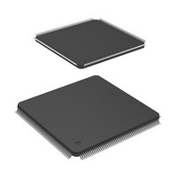
HD6417705F133BV Renesas Electronics America, HD6417705F133BV Datasheet - Page 315

HD6417705F133BV
Manufacturer Part Number
HD6417705F133BV
Description
MPU 3V 0K PB-FREE 208 FP
Manufacturer
Renesas Electronics America
Series
SuperH® SH7700r
Datasheet
1.HD6417705F133BV.pdf
(741 pages)
Specifications of HD6417705F133BV
Core Processor
SH-3
Core Size
32-Bit
Speed
133MHz
Connectivity
EBI/EMI, FIFO, IrDA, SCI, USB
Peripherals
DMA, POR, PWM, WDT
Number Of I /o
105
Program Memory Type
ROMless
Ram Size
32K x 8
Voltage - Supply (vcc/vdd)
1.4 V ~ 1.6 V
Data Converters
A/D 4x10b
Oscillator Type
Internal
Operating Temperature
-20°C ~ 75°C
Package / Case
208-LQFP
Lead Free Status / RoHS Status
Lead free / RoHS Compliant
Eeprom Size
-
Program Memory Size
-
- Current page: 315 of 741
- Download datasheet (5Mb)
On the other hand, if channel 0 is operating in cycle-steal mode, channel 1 will begin operating
again after channel 0 completes the transfer of one transfer unit, and without the internal bus being
released. Transfer will then alternate between the two channels in the order channel 0, channel 1,
channel 0, channel 1, and so on. In other words, the CPU cycles following cycle-steal mode
transfer are replaced by bust mode transfer. Figure 8.12 shows an example of this. If multiple
channels are competing to execute burst mode transfers, the channel with the highest priority
performs the burst mode transfer first.
When DMA transfers are performed using multiple channels, the bus is not released to another bus
master until all of the competing burst mode transfers have completed.
Cycle-steal mode channels and burst mode channels should not be mixed in round-robin mode.
Doing so runs the risk that priority changes may not be made properly, although the individual
channel transfer operations will be performed correctly.
8.4.5
Number of Bus Cycle States: When the DMAC is the bus master, the number of bus cycle states
is controlled by the bus state controller (BSC) in the same way as when the CPU is the bus master.
For details, see section 7, Bus State Controller (BSC).
DREQ Pin Sampling Timing:
Figure 8.13 Example of DREQ Input Detection in Cycle Steal Mode Edge Detection
Priority: CH0 > CH1
CH0: Cycle-steal mode
CH1: Burst mode
CPU
CPU
Number of Bus Cycle States and DREQ Pin Sampling Timing
DMA CH1
Figure 8.12 Bus State when Multiple Channels are Operating
CKIO
Bus cycle
DREQ
(Rising)
DACK
(Active-high)
DMAC CH1
burst mode
DMA CH1
DMA CH0
1st acceptance
CH0
CPU
Cycle-steal mode between
DMAC CH0 and CH1
Non sensitive period
DMA CH1
CH1
CPU
DMA CH0
CH0
DMAC
Acceptance start
2nd acceptance
Rev. 2.00, 09/03, page 267 of 690
DMA CH1
DMAC CH1
burst mode
CPU
DMA CH1
CPU
CPU
Related parts for HD6417705F133BV
Image
Part Number
Description
Manufacturer
Datasheet
Request
R

Part Number:
Description:
KIT STARTER FOR M16C/29
Manufacturer:
Renesas Electronics America
Datasheet:

Part Number:
Description:
KIT STARTER FOR R8C/2D
Manufacturer:
Renesas Electronics America
Datasheet:

Part Number:
Description:
R0K33062P STARTER KIT
Manufacturer:
Renesas Electronics America
Datasheet:

Part Number:
Description:
KIT STARTER FOR R8C/23 E8A
Manufacturer:
Renesas Electronics America
Datasheet:

Part Number:
Description:
KIT STARTER FOR R8C/25
Manufacturer:
Renesas Electronics America
Datasheet:

Part Number:
Description:
KIT STARTER H8S2456 SHARPE DSPLY
Manufacturer:
Renesas Electronics America
Datasheet:

Part Number:
Description:
KIT STARTER FOR R8C38C
Manufacturer:
Renesas Electronics America
Datasheet:

Part Number:
Description:
KIT STARTER FOR R8C35C
Manufacturer:
Renesas Electronics America
Datasheet:

Part Number:
Description:
KIT STARTER FOR R8CL3AC+LCD APPS
Manufacturer:
Renesas Electronics America
Datasheet:

Part Number:
Description:
KIT STARTER FOR RX610
Manufacturer:
Renesas Electronics America
Datasheet:

Part Number:
Description:
KIT STARTER FOR R32C/118
Manufacturer:
Renesas Electronics America
Datasheet:

Part Number:
Description:
KIT DEV RSK-R8C/26-29
Manufacturer:
Renesas Electronics America
Datasheet:

Part Number:
Description:
KIT STARTER FOR SH7124
Manufacturer:
Renesas Electronics America
Datasheet:

Part Number:
Description:
KIT STARTER FOR H8SX/1622
Manufacturer:
Renesas Electronics America
Datasheet:

Part Number:
Description:
KIT DEV FOR SH7203
Manufacturer:
Renesas Electronics America
Datasheet:


