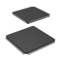
HD6417705F133BV Renesas Electronics America, HD6417705F133BV Datasheet - Page 47

HD6417705F133BV
Manufacturer Part Number
HD6417705F133BV
Description
MPU 3V 0K PB-FREE 208 FP
Manufacturer
Renesas Electronics America
Series
SuperH® SH7700r
Datasheet
1.HD6417705F133BV.pdf
(741 pages)
Specifications of HD6417705F133BV
Core Processor
SH-3
Core Size
32-Bit
Speed
133MHz
Connectivity
EBI/EMI, FIFO, IrDA, SCI, USB
Peripherals
DMA, POR, PWM, WDT
Number Of I /o
105
Program Memory Type
ROMless
Ram Size
32K x 8
Voltage - Supply (vcc/vdd)
1.4 V ~ 1.6 V
Data Converters
A/D 4x10b
Oscillator Type
Internal
Operating Temperature
-20°C ~ 75°C
Package / Case
208-LQFP
Lead Free Status / RoHS Status
Lead free / RoHS Compliant
Eeprom Size
-
Program Memory Size
-
- Current page: 47 of 741
- Download datasheet (5Mb)
Table 20.10
Table 20.11
Table 20.12
Table 20.13
Table 20.14
Section 21 A/D Converter
Table 21.1
Table 21.2
Table 21.3
Table 21.4
Table 21.5
Table 21.6
Section 22 User Break Controller
Table 22.1
Section 23 User Debugging Interface (UDI)
Table 23.1
Table 23.2
Table 23.3
Table 23.4
Section 25 Electrical Characteristics
Table 25.1
Table 25.2
Table 25.2
Table 25.2
Table 25.2
Table 25.3
Table 25.4
Table 25.5
Table 25.6
Table 25.7
Table 25.8
Table 25.9
Table 25.10
Table 25.11
Table 25.12
Table 25.13
Table 25.14
Table 25.15
Table 25.16
Table 25.17
Table 25.18
Port K Data Register (PKDR) Read/Write Operations ....................................... 520
Port L Data Register (PLDR) Read/Write Operation ......................................... 521
Port M Data Register (PMDR) Read/Write Operations...................................... 522
Port N Data Register (PNDR) Read/Write Operations ....................................... 524
SC Port Data Register (SCPDR) Read/Write Operations ................................... 525
Pin Configuration ............................................................................................. 529
Analog Input Channels and A/D Data Registers ................................................ 530
A/D Conversion Time (Single Mode)................................................................ 535
A/D Conversion Time (Multi Mode and Scan Mode) ........................................ 535
A/D Converter Interrupt Source ........................................................................ 536
Analog Input Pin Ratings.................................................................................. 540
Data Access Cycle Addresses and Operand Size Comparison Conditions .......... 558
Pin Configuration ............................................................................................. 568
UDI Commands ............................................................................................... 570
SH7705 Pins and Boundary Scan Register Bits ................................................. 571
Reset Configuration.......................................................................................... 579
Absolute Maximum Ratings ............................................................................. 623
DC Characteristics (1) [Common Items] ........................................................... 625
DC Characteristics (2-a) [Excluding USB-Related Pins].................................... 627
DC Characteristics (2-b) [USB-Related Pins*] .................................................. 628
DC Characteristics (2-c) [USB Transceiver-Related Pins*
Permitted Output Current Values ...................................................................... 629
Maximum Operating Frequencies ..................................................................... 630
Clock Timing ................................................................................................... 631
Control Signal Timing ...................................................................................... 636
Bus Timing (1) ................................................................................................. 638
Bus Timing (2) ................................................................................................. 663
DMAC Signal Timing ...................................................................................... 668
TMU Signal Timing ......................................................................................... 669
RTC Signal Timing .......................................................................................... 670
16-Bit Timer Pulse Unit (TPU) Signal Timing .................................................. 670
SCIF Module Signal Timing............................................................................. 671
USB Module Clock Timing .............................................................................. 672
USB Transceiver Timing .................................................................................. 673
Port Input/Output Timing ................................................................................. 674
UDI Related Pin Timing ................................................................................... 675
A/D Converter Characteristics .......................................................................... 678
Rev. 2.00, 09/03, page xlv of xlvi
1
] .............................. 629
Related parts for HD6417705F133BV
Image
Part Number
Description
Manufacturer
Datasheet
Request
R

Part Number:
Description:
KIT STARTER FOR M16C/29
Manufacturer:
Renesas Electronics America
Datasheet:

Part Number:
Description:
KIT STARTER FOR R8C/2D
Manufacturer:
Renesas Electronics America
Datasheet:

Part Number:
Description:
R0K33062P STARTER KIT
Manufacturer:
Renesas Electronics America
Datasheet:

Part Number:
Description:
KIT STARTER FOR R8C/23 E8A
Manufacturer:
Renesas Electronics America
Datasheet:

Part Number:
Description:
KIT STARTER FOR R8C/25
Manufacturer:
Renesas Electronics America
Datasheet:

Part Number:
Description:
KIT STARTER H8S2456 SHARPE DSPLY
Manufacturer:
Renesas Electronics America
Datasheet:

Part Number:
Description:
KIT STARTER FOR R8C38C
Manufacturer:
Renesas Electronics America
Datasheet:

Part Number:
Description:
KIT STARTER FOR R8C35C
Manufacturer:
Renesas Electronics America
Datasheet:

Part Number:
Description:
KIT STARTER FOR R8CL3AC+LCD APPS
Manufacturer:
Renesas Electronics America
Datasheet:

Part Number:
Description:
KIT STARTER FOR RX610
Manufacturer:
Renesas Electronics America
Datasheet:

Part Number:
Description:
KIT STARTER FOR R32C/118
Manufacturer:
Renesas Electronics America
Datasheet:

Part Number:
Description:
KIT DEV RSK-R8C/26-29
Manufacturer:
Renesas Electronics America
Datasheet:

Part Number:
Description:
KIT STARTER FOR SH7124
Manufacturer:
Renesas Electronics America
Datasheet:

Part Number:
Description:
KIT STARTER FOR H8SX/1622
Manufacturer:
Renesas Electronics America
Datasheet:

Part Number:
Description:
KIT DEV FOR SH7203
Manufacturer:
Renesas Electronics America
Datasheet:


