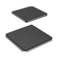
HD6417705F133BV Renesas Electronics America, HD6417705F133BV Datasheet - Page 37

HD6417705F133BV
Manufacturer Part Number
HD6417705F133BV
Description
MPU 3V 0K PB-FREE 208 FP
Manufacturer
Renesas Electronics America
Series
SuperH® SH7700r
Datasheet
1.HD6417705F133BV.pdf
(741 pages)
Specifications of HD6417705F133BV
Core Processor
SH-3
Core Size
32-Bit
Speed
133MHz
Connectivity
EBI/EMI, FIFO, IrDA, SCI, USB
Peripherals
DMA, POR, PWM, WDT
Number Of I /o
105
Program Memory Type
ROMless
Ram Size
32K x 8
Voltage - Supply (vcc/vdd)
1.4 V ~ 1.6 V
Data Converters
A/D 4x10b
Oscillator Type
Internal
Operating Temperature
-20°C ~ 75°C
Package / Case
208-LQFP
Lead Free Status / RoHS Status
Lead free / RoHS Compliant
Eeprom Size
-
Program Memory Size
-
- Current page: 37 of 741
- Download datasheet (5Mb)
Section 8 Direct Memory Access Controller (DMAC)
Figure 8.1 Block Diagram of DMAC ..................................................................................... 240
Figure 8.2 DMAC Transfer Flowchart ................................................................................... 253
Figure 8.3 Round-Robin Mode .............................................................................................. 258
Figure 8.4 Channel Priority in Round-Robin Mode ................................................................ 259
Figure 8.5 Data Flow of Dual Address Mode ......................................................................... 261
Figure 8.6 Example of DMA Transfer Timing in Dual Mode
Figure 8.7 Data Flow in Single Address Mode ....................................................................... 263
Figure 8.8 Example of DMA Transfer Timing in Single Address Mode.................................. 263
Figure 8.9 DMA Transfer Example in Cycle-Steal Normal Mode
Figure 8.10 Example of DMA Transfer in Cycle Steal Intermittent Mode
Figure 8.11 DMA Transfer Example in Burst Mode
Figure 8.12 Bus State when Multiple Channels are Operating................................................. 267
Figure 8.13 Example of DREQ Input Detection in Cycle Steal Mode Edge Detection ............. 267
Figure 8.14 Example of DREQ Input Detection in Cycle Steal Mode Level Detection ............ 268
Figure 8.15 Example of DREQ Input Detection in Burst Mode Edge Detection ...................... 268
Figure 8.16 Example of DREQ Input Detection in Burst Mode Level Detection ..................... 269
Figure 8.17 Example of DMA Transfer End Signal (in Cycle Steal Level Detection) .............. 269
Figure 8.18 BSC Ordinary Memory Access
Section 9 Clock Pulse Generator (CPG)
Figure 9.1 Block Diagram of Clock Pulse Generator .............................................................. 272
Figure 9.2 Points for Attention when Using Crystal Resonator ............................................... 283
Figure 9.3 Points for Attention when Using PLL Oscillator Circuit ........................................ 284
Section 10 Watchdog Timer (WDT)
Figure 10.1 Block Diagram of WDT ...................................................................................... 286
Figure 10.2 Writing to WTCNT and WTCSR ........................................................................ 290
Section 11 Power-Down Modes
Figure 11.1 Canceling Standby Mode with STBY Bit in STBCR............................................ 301
Figure 11.2 Power-On Reset STATUS Output ....................................................................... 303
Figure 11.3 Manual Reset STATUS Output ........................................................................... 303
Figure 11.4 Canceling Software Standby by Interrupt STATUS Output.................................. 304
Figure 11.5 Canceling Software Standby by Power-On Reset STATUS Output ...................... 304
Figure 11.6 Canceling Software Standby by Manual Reset STATUS Output .......................... 305
Figure 11.7 Canceling Sleep by Interrupt STATUS Output .................................................... 305
Figure 11.8 Canceling Sleep by Power-On Reset STATUS Output......................................... 306
Figure 11.9 Canceling Sleep by Manual Reset STATUS Output............................................. 306
(Source: Ordinary Memory, Destination: Ordinary Memory).................................. 262
(Dual Address, DREQ Low Level Detection)......................................................... 264
(Dual Address, DREQ Low Level Detection)....................................................... 265
(Dual Address, DREQ Low Level Detection)....................................................... 265
(No Wait, Idle Cycle 1, Longword Access to 16-Bit Device) ................................ 270
Rev. 2.00, 09/03, page xxxv of xlvi
Related parts for HD6417705F133BV
Image
Part Number
Description
Manufacturer
Datasheet
Request
R

Part Number:
Description:
KIT STARTER FOR M16C/29
Manufacturer:
Renesas Electronics America
Datasheet:

Part Number:
Description:
KIT STARTER FOR R8C/2D
Manufacturer:
Renesas Electronics America
Datasheet:

Part Number:
Description:
R0K33062P STARTER KIT
Manufacturer:
Renesas Electronics America
Datasheet:

Part Number:
Description:
KIT STARTER FOR R8C/23 E8A
Manufacturer:
Renesas Electronics America
Datasheet:

Part Number:
Description:
KIT STARTER FOR R8C/25
Manufacturer:
Renesas Electronics America
Datasheet:

Part Number:
Description:
KIT STARTER H8S2456 SHARPE DSPLY
Manufacturer:
Renesas Electronics America
Datasheet:

Part Number:
Description:
KIT STARTER FOR R8C38C
Manufacturer:
Renesas Electronics America
Datasheet:

Part Number:
Description:
KIT STARTER FOR R8C35C
Manufacturer:
Renesas Electronics America
Datasheet:

Part Number:
Description:
KIT STARTER FOR R8CL3AC+LCD APPS
Manufacturer:
Renesas Electronics America
Datasheet:

Part Number:
Description:
KIT STARTER FOR RX610
Manufacturer:
Renesas Electronics America
Datasheet:

Part Number:
Description:
KIT STARTER FOR R32C/118
Manufacturer:
Renesas Electronics America
Datasheet:

Part Number:
Description:
KIT DEV RSK-R8C/26-29
Manufacturer:
Renesas Electronics America
Datasheet:

Part Number:
Description:
KIT STARTER FOR SH7124
Manufacturer:
Renesas Electronics America
Datasheet:

Part Number:
Description:
KIT STARTER FOR H8SX/1622
Manufacturer:
Renesas Electronics America
Datasheet:

Part Number:
Description:
KIT DEV FOR SH7203
Manufacturer:
Renesas Electronics America
Datasheet:


