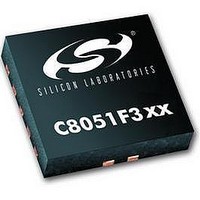
C8051F302 Silicon Laboratories Inc, C8051F302 Datasheet - Page 111

C8051F302
Manufacturer Part Number
C8051F302
Description
IC 8051 MCU 8K FLASH 11MLP
Manufacturer
Silicon Laboratories Inc
Series
C8051F30xr
Specifications of C8051F302
Core Processor
8051
Core Size
8-Bit
Speed
25MHz
Connectivity
SMBus (2-Wire/I²C), UART/USART
Peripherals
POR, PWM, Temp Sensor, WDT
Number Of I /o
8
Program Memory Size
8KB (8K x 8)
Program Memory Type
FLASH
Ram Size
256 x 8
Voltage - Supply (vcc/vdd)
2.7 V ~ 3.6 V
Data Converters
A/D 8x8b
Oscillator Type
External
Operating Temperature
-40°C ~ 85°C
Package / Case
11-VQFN
Data Bus Width
8 bit
Data Ram Size
256 B
Interface Type
I2C, SMBus, UART
Maximum Clock Frequency
25 MHz
Number Of Programmable I/os
8
Number Of Timers
16 bit
Operating Supply Voltage
2.7 V to 3.6 V
Maximum Operating Temperature
+ 85 C
Mounting Style
SMD/SMT
Minimum Operating Temperature
- 40 C
On-chip Adc
8 bit
Lead Free Status / RoHS Status
Contains lead / RoHS non-compliant
Eeprom Size
-
Lead Free Status / Rohs Status
No
Available stocks
Company
Part Number
Manufacturer
Quantity
Price
Company:
Part Number:
C8051F302-GMR
Manufacturer:
SiliconL
Quantity:
3 000
Company:
Part Number:
C8051F302-GMR
Manufacturer:
SILICON
Quantity:
5 000
Part Number:
C8051F302-GMR
Manufacturer:
SILICONLABS/èٹ¯ç§‘
Quantity:
20 000
C8051F300/1/2/3/4/5
13.4.2. SMB0CN Control Register
SMB0CN is used to control the interface and to provide status information (see Figure 13.6). The higher four bits of
SMB0CN (MASTER, TXMODE, STA, and STO) form a status vector that can be used to jump to service routines.
MASTER and TXMODE indicate the master/slave state and transmit/receive modes, respectively.
The STA bit indicates that a START has been detected or generated since the last SMBus interrupt. When set to ‘1’,
the STA bit will cause the SMBus to enter Master mode and generate a START when the bus becomes free. STA is
not cleared by hardware after the START is generated; it must be cleared by software.
As a master, writing the STO bit will cause the hardware to generate a STOP condition and end the current transfer
after the next ACK cycle. STO is cleared by hardware after the STOP condition is generated. As a slave, STO indi-
cates that a STOP condition has been detected since the last SMBus interrupt. STO is also used in slave mode to man-
age the transition from slave receiver to slave transmitter; see
Section 13.5.4
for details on this procedure.
If STO and STA are both set to ‘1’ (while in Master Mode), a STOP followed by a START will be generated.
As a receiver, writing the ACK bit defines the outgoing ACK value; as a transmitter, reading the ACK bit indicates
the value received on the last ACK cycle. ACKRQ is set each time a byte is received, indicating that an outgoing
ACK value is needed. When ACKRQ is set, software should write the desired outgoing value to the ACK bit before
clearing SI. A NACK will be generated if software does not write the ACK bit before clearing SI. SDA will reflect
the defined ACK value immediately following a write to the ACK bit; however SCL will remain low until SI is
cleared. If a received slave address is not acknowledged, further slave events will be ignored until the next START is
detected.
The ARBLOST bit indicates that the interface has lost an arbitration. This may occur anytime the interface is trans-
mitting (master or slave). A lost arbitration while operating as a slave indicates a bus error condition. ARBLOST is
cleared by hardware each time SI is cleared.
The SI bit (SMBus Interrupt Flag) is set at the beginning and end of each transfer, after each byte frame, or when an
arbitration is lost; see Table 13.3 for more details.
Important Note About the SI Bit: The SMBus interface is stalled while SI is set; thus SCL is held low, and the bus
is stalled until software clears SI.
Table 13.3 lists all sources for hardware changes to the SMB0CN bits. Refer to Table 13.4 for SMBus status decoding
using the SMB0CN register.
Rev. 2.3
111


