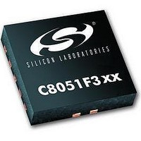
C8051F302 Silicon Laboratories Inc, C8051F302 Datasheet - Page 15

C8051F302
Manufacturer Part Number
C8051F302
Description
IC 8051 MCU 8K FLASH 11MLP
Manufacturer
Silicon Laboratories Inc
Series
C8051F30xr
Specifications of C8051F302
Core Processor
8051
Core Size
8-Bit
Speed
25MHz
Connectivity
SMBus (2-Wire/I²C), UART/USART
Peripherals
POR, PWM, Temp Sensor, WDT
Number Of I /o
8
Program Memory Size
8KB (8K x 8)
Program Memory Type
FLASH
Ram Size
256 x 8
Voltage - Supply (vcc/vdd)
2.7 V ~ 3.6 V
Data Converters
A/D 8x8b
Oscillator Type
External
Operating Temperature
-40°C ~ 85°C
Package / Case
11-VQFN
Data Bus Width
8 bit
Data Ram Size
256 B
Interface Type
I2C, SMBus, UART
Maximum Clock Frequency
25 MHz
Number Of Programmable I/os
8
Number Of Timers
16 bit
Operating Supply Voltage
2.7 V to 3.6 V
Maximum Operating Temperature
+ 85 C
Mounting Style
SMD/SMT
Minimum Operating Temperature
- 40 C
On-chip Adc
8 bit
Lead Free Status / RoHS Status
Contains lead / RoHS non-compliant
Eeprom Size
-
Lead Free Status / Rohs Status
No
Available stocks
Company
Part Number
Manufacturer
Quantity
Price
Company:
Part Number:
C8051F302-GMR
Manufacturer:
SiliconL
Quantity:
3 000
Company:
Part Number:
C8051F302-GMR
Manufacturer:
SILICON
Quantity:
5 000
Part Number:
C8051F302-GMR
Manufacturer:
SILICONLABS/èٹ¯ç§‘
Quantity:
20 000
1.1.3. Additional Features
The C8051F300/1/2/3/4/5 SoC family includes several key enhancements to the CIP-51 core and peripherals to
improve performance and ease of use in end applications.
The extended interrupt handler provides 12 interrupt sources into the CIP-51 (as opposed to 7 for the standard 8051),
allowing numerous analog and digital peripherals to interrupt the controller. An interrupt driven system requires less
intervention by the MCU, giving it more effective throughput. The extra interrupt sources are very useful when build-
ing multi-tasking, real-time systems.
Eight reset sources are available: power-on reset circuitry (POR), an on-chip VDD monitor (forces reset when power
supply voltage drops below 2.7 V), a Watchdog Timer, a Missing Clock Detector, a voltage level detection from
Comparator0, a forced software reset, an external reset pin, and an illegal FLASH read/write protection circuit. Each
reset source except for the POR, Reset Input Pin, or FLASH protection may be disabled by the user in software. The
WDT may be permanently enabled in software after a power-on reset during MCU initialization.
The internal oscillator is available as a factory calibrated 24.5 MHz ±2% (C8051F300/1 devices); an uncalibrated
version is available on C8051F302/3/4/5 devices. On all C8051F300/1/2/3/4/5 devices, the internal oscillator period
may be user programmed in ~0.5% increments. An external oscillator drive circuit is also included, allowing an
external crystal, ceramic resonator, capacitor, RC, or CMOS clock source to generate the system clock. If desired, the
system clock source may be switched on-the-fly to the external oscillator circuit. An external oscillator can be
extremely useful in low power applications, allowing the MCU to run from a slow (power saving) external crystal
source, while periodically switching to the fast (up to 25 MHz) internal oscillator as needed.
XTAL1
XTAL2
Oscillator
Oscillator
External
Internal
Drive
P0.x
P0.y
Clock Select
System
Clock
Figure 1.4. On-Chip Clock and Reset
Comparator 0
+
-
Detector
Missing
Clock
(one-
shot)
Microcontroller
EN
Extended Interrupt
C0RSEF
CIP-51
Handler
Core
VDD
WDT
PCA
EN
Supply
Monitor
+
-
System Reset
Rev. 2.3
Enable
Power On
Reset
(Software Reset)
SWRSF
C8051F300/1/2/3/4/5
'0'
Operation
FLASH
Illegal
(wired-OR)
Reset
Funnel
/RST
15


