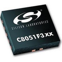
C8051F302 Silicon Laboratories Inc, C8051F302 Datasheet - Page 142

C8051F302
Manufacturer Part Number
C8051F302
Description
IC 8051 MCU 8K FLASH 11MLP
Manufacturer
Silicon Laboratories Inc
Series
C8051F30xr
Specifications of C8051F302
Core Processor
8051
Core Size
8-Bit
Speed
25MHz
Connectivity
SMBus (2-Wire/I²C), UART/USART
Peripherals
POR, PWM, Temp Sensor, WDT
Number Of I /o
8
Program Memory Size
8KB (8K x 8)
Program Memory Type
FLASH
Ram Size
256 x 8
Voltage - Supply (vcc/vdd)
2.7 V ~ 3.6 V
Data Converters
A/D 8x8b
Oscillator Type
External
Operating Temperature
-40°C ~ 85°C
Package / Case
11-VQFN
Data Bus Width
8 bit
Data Ram Size
256 B
Interface Type
I2C, SMBus, UART
Maximum Clock Frequency
25 MHz
Number Of Programmable I/os
8
Number Of Timers
16 bit
Operating Supply Voltage
2.7 V to 3.6 V
Maximum Operating Temperature
+ 85 C
Mounting Style
SMD/SMT
Minimum Operating Temperature
- 40 C
On-chip Adc
8 bit
Lead Free Status / RoHS Status
Contains lead / RoHS non-compliant
Eeprom Size
-
Lead Free Status / Rohs Status
No
Available stocks
Company
Part Number
Manufacturer
Quantity
Price
Company:
Part Number:
C8051F302-GMR
Manufacturer:
SiliconL
Quantity:
3 000
Company:
Part Number:
C8051F302-GMR
Manufacturer:
SILICON
Quantity:
5 000
Part Number:
C8051F302-GMR
Manufacturer:
SILICONLABS/èٹ¯ç§‘
Quantity:
20 000
C8051F300/1/2/3/4/5
15.2.2. 8-bit Timers with Auto-Reload
When T2SPLIT is set, Timer 2 operates as two 8-bit timers (TMR2H and TMR2L). Both 8-bit timers operate in auto-
reload mode as shown in Figure 15.12. TMR2RLL holds the reload value for TMR2L; TMR2RLH holds the reload
value for TMR2H. The TR2 bit in TMR2CN handles the run control for TMR2H. TMR2L is always running when
configured for 8-bit Mode.
Each 8-bit timer may be configured to use SYSCLK, SYSCLK divided by 12, or the external oscillator clock source
divided by 8. The Timer 2 Clock Select bits (T2MH and T2ML in CKCON) select either SYSCLK or the clock
defined by the Timer 2 External Clock Select bit (T2XCLK in TMR2CN), as follows:
Note: External clock divided by 8 is synchronized with the system clock, and the external clock must be less than or
equal to the system clock to operate in this mode.
The TF2H bit is set when TMR2H overflows from 0xFF to 0x00; the TF2L bit is set when TMR2L overflows from
0xFF to 0x00. When Timer 2 interrupts are enabled (IE.5), an interrupt is generated each time TMR2H overflows. If
Timer 2 interrupts are enabled and TF2LEN (TMR2CN.5) is set, an interrupt is generated each time either TMR2L or
TMR2H overflows. When TF2LEN is enabled, software must check the TF2H and TF2L flags to determine the
source of the Timer 2 interrupt. The TF2H and TF2L interrupt flags are not cleared by hardware and must be manu-
ally cleared by software.
142
External Clock / 8
T2MH
SYSCLK / 12
0
0
1
T2XCLK
T2XCLK
X
0
1
0
1
Figure 15.12. Timer 2 8-Bit Mode Block Diagram
SYSCLK
TH2 Clock Source
External Clock / 8
SYSCLK / 12
SYSCLK
0
1
1
0
M
H
T
2
CKCON
M
T
2
L
M
T
1
M
T
0
TR2
C
S
A
1
S
C
A
0
Rev. 2.3
TCLK
TCLK
TMR2RLH
TMR2RLL
TMR2H
TMR2L
T2ML
Reload
Reload
0
0
1
T2XCLK
To SMBus
To ADC,
T2SPLIT
TF2LEN
T2XCLK
SMBus
X
0
1
TF2H
TF2L
TR2
TL2 Clock Source
External Clock / 8
SYSCLK / 12
SYSCLK
Interrupt


