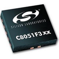
C8051F302 Silicon Laboratories Inc, C8051F302 Datasheet - Page 9

C8051F302
Manufacturer Part Number
C8051F302
Description
IC 8051 MCU 8K FLASH 11MLP
Manufacturer
Silicon Laboratories Inc
Series
C8051F30xr
Specifications of C8051F302
Core Processor
8051
Core Size
8-Bit
Speed
25MHz
Connectivity
SMBus (2-Wire/I²C), UART/USART
Peripherals
POR, PWM, Temp Sensor, WDT
Number Of I /o
8
Program Memory Size
8KB (8K x 8)
Program Memory Type
FLASH
Ram Size
256 x 8
Voltage - Supply (vcc/vdd)
2.7 V ~ 3.6 V
Data Converters
A/D 8x8b
Oscillator Type
External
Operating Temperature
-40°C ~ 85°C
Package / Case
11-VQFN
Data Bus Width
8 bit
Data Ram Size
256 B
Interface Type
I2C, SMBus, UART
Maximum Clock Frequency
25 MHz
Number Of Programmable I/os
8
Number Of Timers
16 bit
Operating Supply Voltage
2.7 V to 3.6 V
Maximum Operating Temperature
+ 85 C
Mounting Style
SMD/SMT
Minimum Operating Temperature
- 40 C
On-chip Adc
8 bit
Lead Free Status / RoHS Status
Contains lead / RoHS non-compliant
Eeprom Size
-
Lead Free Status / Rohs Status
No
Available stocks
Company
Part Number
Manufacturer
Quantity
Price
Company:
Part Number:
C8051F302-GMR
Manufacturer:
SiliconL
Quantity:
3 000
Company:
Part Number:
C8051F302-GMR
Manufacturer:
SILICON
Quantity:
5 000
Part Number:
C8051F302-GMR
Manufacturer:
SILICONLABS/èٹ¯ç§‘
Quantity:
20 000
12. PORT INPUT/OUTPUT
13. SMBUS
14. UART0
15. TIMERS
Figure 11.4. OSCXCN: External Oscillator Control Register.................................................92
Figure 12.1. Port I/O Functional Block Diagram ....................................................................95
Figure 12.2. Port I/O Cell Block Diagram...............................................................................95
Figure 12.3. Crossbar Priority Decoder with XBR0 = 0x00 ...................................................96
Figure 12.4. Crossbar Priority Decoder with XBR0 = 0x44 ...................................................97
Figure 12.5. XBR0: Port I/O Crossbar Register 0 ...................................................................99
Figure 12.6. XBR1: Port I/O Crossbar Register 1 ...................................................................99
Figure 12.7. XBR2: Port I/O Crossbar Register 2 .................................................................100
Figure 12.8. P0: Port0 Register..............................................................................................101
Figure 12.9. P0MDIN: Port0 Input Mode Register ...............................................................101
Figure 12.10. P0MDOUT: Port0 Output Mode Register.......................................................102
Table 12.1. Port I/O DC Electrical Characteristics ..............................................................102
Figure 13.1. SMBus Block Diagram .....................................................................................103
Figure 13.2. Typical SMBus Configuration ..........................................................................104
Figure 13.3. SMBus Transaction ...........................................................................................105
Table 13.1. SMBus Clock Source Selection.........................................................................108
Figure 13.4. Typical SMBus SCL Generation.......................................................................108
Table 13.2. Minimum SDA Setup and Hold Times .............................................................109
Figure 13.5. SMB0CF: SMBus Clock/Configuration Register .............................................110
Figure 13.6. SMB0CN: SMBus Control Register .................................................................112
Table 13.3. Sources for Hardware Changes to SMB0CN ....................................................113
Figure 13.7. SMB0DAT: SMBus Data Register ...................................................................114
Figure 13.8. Typical Master Transmitter Sequence...............................................................115
Figure 13.9. Typical Master Receiver Sequence ...................................................................116
Figure 13.10. Typical Slave Receiver Sequence ...................................................................117
Figure 13.11. Typical Slave Transmitter Sequence ...............................................................118
Table 13.4. SMBus Status Decoding....................................................................................119
Figure 14.1. UART0 Block Diagram.....................................................................................123
Figure 14.2. UART0 Baud Rate Logic ..................................................................................124
Figure 14.3. UART Interconnect Diagram ............................................................................125
Figure 14.4. 8-Bit UART Timing Diagram ...........................................................................125
Figure 14.5. 9-Bit UART Timing Diagram ...........................................................................126
Figure 14.6. UART Multi-Processor Mode Interconnect Diagram .......................................127
Figure 14.7. SCON0: Serial Port 0 Control Register.............................................................128
Figure 14.8. SBUF0: Serial (UART0) Port Data Buffer Register .........................................129
Table 14.1. Timer Settings for Standard Baud Rates Using The Internal Oscillator ...........130
Table 14.2. Timer Settings for Standard Baud Rates Using an External Oscillator.............130
Table 14.3. Timer Settings for Standard Baud Rates Using an External Oscillator.............131
Table 14.4. Timer Settings for Standard Baud Rates Using an External Oscillator.............131
Table 14.5. Timer Settings for Standard Baud Rates Using an External Oscillator.............132
Table 14.6. Timer Settings for Standard Baud Rates Using an External Oscillator.............132
Rev. 2.3
C8051F300/1/2/3/4/5
9


