NNDK-MOD5272-KIT NetBurner Inc, NNDK-MOD5272-KIT Datasheet - Page 133
NNDK-MOD5272-KIT
Manufacturer Part Number
NNDK-MOD5272-KIT
Description
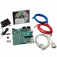
KIT DEVELOP NETWORK FOR MOD5272
Manufacturer
NetBurner Inc
Series
ColdFire®r
Datasheets
1.MOD5272-100IR.pdf
(2 pages)
2.MOD5272-100IR.pdf
(550 pages)
3.NNDK-MOD5282-KIT.pdf
(2 pages)
Specifications of NNDK-MOD5272-KIT
Main Purpose
*
Embedded
*
Utilized Ic / Part
MOD5272
Primary Attributes
*
Secondary Attributes
*
Processor To Be Evaluated
MOD5272
Interface Type
RS-232, RS-485, USB
Lead Free Status / RoHS Status
Contains lead / RoHS non-compliant
Lead Free Status / RoHS Status
Lead free / RoHS Compliant, Contains lead / RoHS non-compliant
Other names
528-1001


MOTOROLA
5.4.5 Data Breakpoint/Mask Registers (DBR, DBMR)
The data breakpoint register (DBR), Figure 5-8, specify data patterns used as part of the
trigger into debug mode. DBR bits are masked by setting corresponding DBMR bits, as
defined in TDR.
12–11
9–8
3–0
Bit
13
10
7
6
5
4
Name
EMU
DDC
UHE
SSM
BTB
NPL
IPI
—
—
Force emulation mode. If EMU = 1, the processor begins executing in emulator mode. See
Section 5.6.1.1, “Emulator Mode.”
Debug data control. Controls operand data capture for DDATA, which displays the number of bytes
defined by the operand reference size before the actual data; byte displays 8 bits, word displays 16
bits, and long displays 32 bits (one nibble at a time across multiple clock cycles). See Table 5-2.
00 No operand data is displayed.
01 Capture all write data.
10 Capture all read data.
11 Capture all read and write data.
User halt enable. Selects the CPU privilege level required to execute the HALT instruction.
0 HALT is a supervisor-only instruction.
1 HALT is a supervisor/user instruction.
Branch target bytes. Defines the number of bytes of branch target address DDATA displays.
00 0 bytes
01 Lower 2 bytes of the target address
10 Lower 3 bytes of the target address
11 Entire 4-byte target address
See Section 5.3.1, “Begin Execution of Taken Branch (PST = 0x5).”
Reserved, should be cleared.
Non- mode. Determines whether the core operates in pipelined or mode or not.
0 Pipelined mode
1 Nonpipelined mode. The processor effectively executes one instruction at a time with no overlap.
Regardless of the NPL state, a triggered PC breakpoint is always reported before the triggering
instruction executes. In normal pipeline operation, the occurrence of an address and/or data
breakpoint trigger is imprecise. In non-pipeline mode, triggers are always reported before the next
instruction begins execution and trigger reporting can be considered precise.
An address or data breakpoint should always occur before the next instruction begins execution.
Therefore the occurrence of the address/data breakpoints should be guaranteed.
Ignore pending interrupts.
1 Core ignores any pending interrupt requests signalled while in single-instruction-step mode.
0 Core services any pending interrupt requests that were signalled while in single-step mode.
Single-step mode. Setting SSM puts the processor in single-step mode.
0 Normal mode.
1 Single-step mode. The processor halts after execution of each instruction. While halted, any
Reserved, should be cleared.
This adds at least 5 cycles to the execution time of each instruction. Given an average execution
latency of 1.6, throughput in non-pipeline mode would be 6.6, approximately 25% or less of
pipelined performance.
BDM command can be executed. On receipt of the
next instruction and halts again. This process continues until SSM is cleared.
Table 5-8. CSR Field Descriptions (Continued)
Chapter 5. Debug Support
Description
GO
command, the processor executes the
Programming Model
5-11
Related parts for NNDK-MOD5272-KIT
Image
Part Number
Description
Manufacturer
Datasheet
Request
R

Part Number:
Description:
BOARD SERIAL-ETHERNET 512K FLASH
Manufacturer:
NetBurner Inc
Datasheet:

Part Number:
Description:
PROCESSOR MODULE FLASH MOD5272
Manufacturer:
NetBurner Inc
Datasheet:

Part Number:
Description:
PROCESSOR MODULE 512KB FLASH
Manufacturer:
NetBurner Inc
Datasheet:

Part Number:
Description:
DUAL PORT SERIAL-ETHERNET
Manufacturer:
NetBurner Inc
Datasheet:

Part Number:
Description:
PROCESSOR MODULE FLASH
Manufacturer:
NetBurner Inc
Datasheet:

Part Number:
Description:
PROCESSOR MODULE 512KB FLASH
Manufacturer:
NetBurner Inc
Datasheet:

Part Number:
Description:
MOD5234 10/100 ETHERNET MODULE
Manufacturer:
NetBurner Inc
Datasheet:

Part Number:
Description:
KIT DEVELOP NETWORK FOR MOD5282
Manufacturer:
NetBurner Inc
Datasheet:

Part Number:
Description:
DUAL PORT SERIAL-ETHERNET
Manufacturer:
NetBurner Inc
Datasheet:

Part Number:
Description:
Ethernet Modules & Development Tools 32 Bit 66MHz 40 Pin DIP Industrial Temp
Manufacturer:
NetBurner Inc
Datasheet:

Part Number:
Description:
Ethernet Modules & Development Tools MOD5213 DEVELOPMENT KIT
Manufacturer:
NetBurner Inc

Part Number:
Description:
Ethernet Modules & Development Tools DUAL PORT SERIAL EHTERNET DEVICE
Manufacturer:
NetBurner Inc
Datasheet:

Part Number:
Description:
Ethernet ICs 32bit 147MHz CAN-to- Ethnt Device IndTemp
Manufacturer:
NetBurner Inc
Datasheet: