NNDK-MOD5272-KIT NetBurner Inc, NNDK-MOD5272-KIT Datasheet - Page 334
NNDK-MOD5272-KIT
Manufacturer Part Number
NNDK-MOD5272-KIT
Description
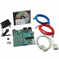
KIT DEVELOP NETWORK FOR MOD5272
Manufacturer
NetBurner Inc
Series
ColdFire®r
Datasheets
1.MOD5272-100IR.pdf
(2 pages)
2.MOD5272-100IR.pdf
(550 pages)
3.NNDK-MOD5282-KIT.pdf
(2 pages)
Specifications of NNDK-MOD5272-KIT
Main Purpose
*
Embedded
*
Utilized Ic / Part
MOD5272
Primary Attributes
*
Secondary Attributes
*
Processor To Be Evaluated
MOD5272
Interface Type
RS-232, RS-485, USB
Lead Free Status / RoHS Status
Contains lead / RoHS non-compliant
Lead Free Status / RoHS Status
Lead free / RoHS Compliant, Contains lead / RoHS non-compliant
Other names
528-1001


FSC1
FSC0
DFSC2
Din0/
Dout0
Application Examples
the CODEC is receiving and transmitting on the B1 or the B2 time slot. See the
MC14LC5480 data sheet for further information.
Figure 13-38 shows the IDL bus timing relationship of the CODECs and MC145574
transceiver when in standard IDL2 10-bit mode with a common frame sync.
DFSC3
Din1/
Dout1
The S/T transceiver is connected to port 0, Din0/Dout0. The DCL and FSC generated from
the S/T transceiver are connected to DCL0, FSC0, and also feed port 1, DCL1, and FSC1
because port 1 is synchronized to these S/T generated timing signals. The six CODECs are
connected to Din1 and Dout1. To provide six discrete 64-Kbps channels on the port 1 IDL
interface, the delayed frame syncs are programmed to synchronize the CODECs on
non-overlapping time slots. CODEC 1 transmits and receives in the B1 time slot. CODEC
2 transmits and receives in the B2 time slot, which starts 10 DCL cycles later, and so on for
the other CODECs. CODECs 3 and 4 are synchronized to DFSC2 which is generated 20
DCL cycles after FSC1 by loading the programmable delay 2 register with 0x0014. The
DFSC3 signal synchronizes CODECs 5 and 6. DFSC3 is generated 40 DCL cycles after
FSC1 by loading the programmable delay 3 register with 0x0028.
Only the port 0 D-channel is used in this example; DREQ0 and DGNT0 are connected to
the S/T transceiver.
The GCI mode of operation is analogous. In GCI mode, port 0 can be configured to support
the SCIT channel.
13-38
DCL
CODEC 1
B1
B1
MC145574
D
Figure 13-38. Standard IDL2 10-Bit Mode
CODEC 2
B2
B2
D
MCF5272 User’s Manual
CODEC 3
B3
CODEC 4
B4
CODEC5
B5
MOTOROLA
CODEC6
B6
Related parts for NNDK-MOD5272-KIT
Image
Part Number
Description
Manufacturer
Datasheet
Request
R

Part Number:
Description:
BOARD SERIAL-ETHERNET 512K FLASH
Manufacturer:
NetBurner Inc
Datasheet:

Part Number:
Description:
PROCESSOR MODULE FLASH MOD5272
Manufacturer:
NetBurner Inc
Datasheet:

Part Number:
Description:
PROCESSOR MODULE 512KB FLASH
Manufacturer:
NetBurner Inc
Datasheet:

Part Number:
Description:
DUAL PORT SERIAL-ETHERNET
Manufacturer:
NetBurner Inc
Datasheet:

Part Number:
Description:
PROCESSOR MODULE FLASH
Manufacturer:
NetBurner Inc
Datasheet:

Part Number:
Description:
PROCESSOR MODULE 512KB FLASH
Manufacturer:
NetBurner Inc
Datasheet:

Part Number:
Description:
MOD5234 10/100 ETHERNET MODULE
Manufacturer:
NetBurner Inc
Datasheet:

Part Number:
Description:
KIT DEVELOP NETWORK FOR MOD5282
Manufacturer:
NetBurner Inc
Datasheet:

Part Number:
Description:
DUAL PORT SERIAL-ETHERNET
Manufacturer:
NetBurner Inc
Datasheet:

Part Number:
Description:
Ethernet Modules & Development Tools 32 Bit 66MHz 40 Pin DIP Industrial Temp
Manufacturer:
NetBurner Inc
Datasheet:

Part Number:
Description:
Ethernet Modules & Development Tools MOD5213 DEVELOPMENT KIT
Manufacturer:
NetBurner Inc

Part Number:
Description:
Ethernet Modules & Development Tools DUAL PORT SERIAL EHTERNET DEVICE
Manufacturer:
NetBurner Inc
Datasheet:

Part Number:
Description:
Ethernet ICs 32bit 147MHz CAN-to- Ethnt Device IndTemp
Manufacturer:
NetBurner Inc
Datasheet: