NNDK-MOD5272-KIT NetBurner Inc, NNDK-MOD5272-KIT Datasheet - Page 184
NNDK-MOD5272-KIT
Manufacturer Part Number
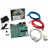
NNDK-MOD5272-KIT
Description
KIT DEVELOP NETWORK FOR MOD5272
Manufacturer
NetBurner Inc
Series
ColdFire®r
Datasheets
1.MOD5272-100IR.pdf
(2 pages)
2.MOD5272-100IR.pdf
(550 pages)
3.NNDK-MOD5282-KIT.pdf
(2 pages)
Specifications of NNDK-MOD5272-KIT
Main Purpose
*
Embedded
*
Utilized Ic / Part
MOD5272
Primary Attributes
*
Secondary Attributes
*
Processor To Be Evaluated
MOD5272
Interface Type
RS-232, RS-485, USB
Lead Free Status / RoHS Status
Contains lead / RoHS non-compliant
Lead Free Status / RoHS Status
Lead free / RoHS Compliant, Contains lead / RoHS non-compliant
Other names
528-1001


Interrupt Controller Registers
Table 7-3 describes ICR3 fields.
7.2.2.4 Interrupt Control Register 4 (ICR4)
ICR4, Figure 7-5, is used to configure interrupts from various on-chip sources.
Table 7-3 describes ICR4 fields.
7.2.3 Interrupt Source Register (ISR)
The interrupt source register (ISR), Figure 7-6, is used to read the instantaneous value of
all interrupt sources, both internal and external. Note that the register bits give the value of
the interrupt source prior to input synchronization or polarity correction.
Reset
Reset
7-6
Field QSPIPI
Field
Addr
R/W
Address
Reset
Reset
Reset
Reset
Field
Field
Field
Field
R/W
R/W
R/W
R/W
31
15
UART1
USB4
QSPI
INT1
31
23
15
7
30
QSPIIPL
Figure 7-5. Interrupt Control Register 4(ICR4)
UART2
USB5
INT2
INT5
Figure 7-6. Interrupt Source Register (ISR)
28
30
22
14
6
INT5PI
27
PLI_P
USB6
INT3
INT6
29
21
13
5
MCF5272 User’s Manual
26
INT5IPL
0000_0000_0000_0000
0000_0000_0000_0000
SWTO
PLI_A
USB7
INT4
MBAR + 0x02C
28
20
12
4
MBAR+0x030
24
XXXX_1111
1XX1_0000
1111_1111
1111_1111
Read only
Read only
Read only
Read only
R/W
—
INT6PI
23
TMR0
USB0
DMA
27
19
11
3
22
INT6IPL
TMR1
USB1
ERx
26
18
10
20
—
SWTOPI
TMR2
USB2
ETx
19
25
17
9
18
SWTOIPL
MOTOROLA
TMR3
ENTC
USB3
24
16
8
0
16
0
Related parts for NNDK-MOD5272-KIT
Image
Part Number
Description
Manufacturer
Datasheet
Request
R

Part Number:
Description:
BOARD SERIAL-ETHERNET 512K FLASH
Manufacturer:
NetBurner Inc
Datasheet:

Part Number:
Description:
PROCESSOR MODULE FLASH MOD5272
Manufacturer:
NetBurner Inc
Datasheet:

Part Number:
Description:
PROCESSOR MODULE 512KB FLASH
Manufacturer:
NetBurner Inc
Datasheet:

Part Number:
Description:
DUAL PORT SERIAL-ETHERNET
Manufacturer:
NetBurner Inc
Datasheet:

Part Number:
Description:
PROCESSOR MODULE FLASH
Manufacturer:
NetBurner Inc
Datasheet:

Part Number:
Description:
PROCESSOR MODULE 512KB FLASH
Manufacturer:
NetBurner Inc
Datasheet:

Part Number:
Description:
MOD5234 10/100 ETHERNET MODULE
Manufacturer:
NetBurner Inc
Datasheet:

Part Number:
Description:
KIT DEVELOP NETWORK FOR MOD5282
Manufacturer:
NetBurner Inc
Datasheet:

Part Number:
Description:
DUAL PORT SERIAL-ETHERNET
Manufacturer:
NetBurner Inc
Datasheet:

Part Number:
Description:
Ethernet Modules & Development Tools 32 Bit 66MHz 40 Pin DIP Industrial Temp
Manufacturer:
NetBurner Inc
Datasheet:

Part Number:
Description:
Ethernet Modules & Development Tools MOD5213 DEVELOPMENT KIT
Manufacturer:
NetBurner Inc

Part Number:
Description:
Ethernet Modules & Development Tools DUAL PORT SERIAL EHTERNET DEVICE
Manufacturer:
NetBurner Inc
Datasheet:

Part Number:
Description:
Ethernet ICs 32bit 147MHz CAN-to- Ethnt Device IndTemp
Manufacturer:
NetBurner Inc
Datasheet: