NNDK-MOD5272-KIT NetBurner Inc, NNDK-MOD5272-KIT Datasheet - Page 315
NNDK-MOD5272-KIT
Manufacturer Part Number
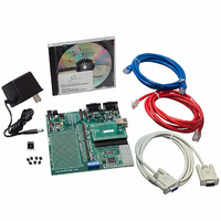
NNDK-MOD5272-KIT
Description
KIT DEVELOP NETWORK FOR MOD5272
Manufacturer
NetBurner Inc
Series
ColdFire®r
Datasheets
1.MOD5272-100IR.pdf
(2 pages)
2.MOD5272-100IR.pdf
(550 pages)
3.NNDK-MOD5282-KIT.pdf
(2 pages)
Specifications of NNDK-MOD5272-KIT
Main Purpose
*
Embedded
*
Utilized Ic / Part
MOD5272
Primary Attributes
*
Secondary Attributes
*
Processor To Be Evaluated
MOD5272
Interface Type
RS-232, RS-485, USB
Lead Free Status / RoHS Status
Contains lead / RoHS non-compliant
Lead Free Status / RoHS Status
Lead free / RoHS Compliant, Contains lead / RoHS non-compliant
Other names
528-1001


MOTOROLA
13.5.7 Port Configuration Registers (P0CR–P3CR)
PnCR are registers containing configuration information for each of the four ports on the
MCF5272.
All bits in these registers are read/write and are cleared on hardware or software reset.
14–12
Bits
P0CR ON/OFF
P1CR ON/OFF
P2CR ON/OFF
P3CR ON/OFF
Reset
10
15
11
Addr
9
R/W
ON/OFF 0 Port is off and in a steady state condition. In this state, the B and D channels on the transmit side
Name
FSM
M/S
G/S
15
M
Figure 13-19. Port Configuration Registers (P0CR–P3CR)
1 Switches on the port for operation in the configured mode.
Mode. Selects between various modes of operation as described below. Note: bit 14 is relevant to
port 0 only. The IDL modes on the PLIC only support short frame sync.
000 IDL8
001 IDL10
010 GCI
011 Reserved Reserved
10x Reserved Reserved
11x Reserved Reserved
Master/Slave. Defines the direction of the DCL1 and FSC1 pins.
0 DCL1 and FSC1 are inputs and are sourced from an external master. Note: This bit is relevant to
1 enables DCL1 and FSC1 to be outputs, that is, the MCF5272 drives DCL1 and FSC1.
GCI/SCIT.
0 The normal mode of GCI is used (i.e. no D-channel contention control).
1 Selects SCIT mode of operation for the GCI interfaces.
Frame Sync Master.
0 Default reset value. 2-KHz interrupt is generated from port 0.
1 Port 1 FSC/FSR is used to generate the 2-KHz interrupt.
—
—
—
14
are high impedance when in GCI/IDL. The receive registers are all set. In IDL and GCI modes
with the port in this state, all periodic and aperiodic interrupts associated with the port are
disabled.
port 1 only, as port 0 is always in slave mode.
Port 1-3
Chapter 13. Physical Layer Interface Controller (PLIC)
—
—
M
MBAR + 0x350 (P0CR); 0x352 (P1CR); 0x354 (P2CR); 0x356 (P3CR)
Table 13-2. P0CR–P3CR Field Descriptions
M
—
—
12
Port 0
IDL8
IDL10
GCI
M/S G/S FSM ACT
—
—
—
11
G/S
—
—
10
0000_0000_0000_0000
—
—
—
9
Read/Write
ACT
—
—
8
Description
DMX —
—
—
—
7
—
—
—
6
—
—
—
—
5
— SHB2 SHB1 ENB2 ENB1
— SHB2 SHB1 ENB2 ENB1
— SHB2 SHB1 ENB2 ENB1
— SHB2 SHB1 ENB2 ENB1
4
3
2
PLIC Registers
1
13-19
0
Related parts for NNDK-MOD5272-KIT
Image
Part Number
Description
Manufacturer
Datasheet
Request
R

Part Number:
Description:
BOARD SERIAL-ETHERNET 512K FLASH
Manufacturer:
NetBurner Inc
Datasheet:

Part Number:
Description:
PROCESSOR MODULE FLASH MOD5272
Manufacturer:
NetBurner Inc
Datasheet:

Part Number:
Description:
PROCESSOR MODULE 512KB FLASH
Manufacturer:
NetBurner Inc
Datasheet:

Part Number:
Description:
DUAL PORT SERIAL-ETHERNET
Manufacturer:
NetBurner Inc
Datasheet:

Part Number:
Description:
PROCESSOR MODULE FLASH
Manufacturer:
NetBurner Inc
Datasheet:

Part Number:
Description:
PROCESSOR MODULE 512KB FLASH
Manufacturer:
NetBurner Inc
Datasheet:

Part Number:
Description:
MOD5234 10/100 ETHERNET MODULE
Manufacturer:
NetBurner Inc
Datasheet:

Part Number:
Description:
KIT DEVELOP NETWORK FOR MOD5282
Manufacturer:
NetBurner Inc
Datasheet:

Part Number:
Description:
DUAL PORT SERIAL-ETHERNET
Manufacturer:
NetBurner Inc
Datasheet:

Part Number:
Description:
Ethernet Modules & Development Tools 32 Bit 66MHz 40 Pin DIP Industrial Temp
Manufacturer:
NetBurner Inc
Datasheet:

Part Number:
Description:
Ethernet Modules & Development Tools MOD5213 DEVELOPMENT KIT
Manufacturer:
NetBurner Inc

Part Number:
Description:
Ethernet Modules & Development Tools DUAL PORT SERIAL EHTERNET DEVICE
Manufacturer:
NetBurner Inc
Datasheet:

Part Number:
Description:
Ethernet ICs 32bit 147MHz CAN-to- Ethnt Device IndTemp
Manufacturer:
NetBurner Inc
Datasheet: