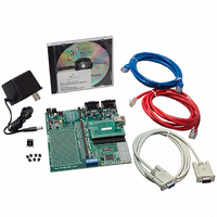
NNDK-MOD5272-KIT NetBurner Inc, NNDK-MOD5272-KIT Datasheet - Page 306

NNDK-MOD5272-KIT
Manufacturer Part Number
NNDK-MOD5272-KIT
Description
KIT DEVELOP NETWORK FOR MOD5272
Manufacturer
NetBurner Inc
Series
ColdFire®r
Datasheets
1.MOD5272-100IR.pdf
(2 pages)
2.MOD5272-100IR.pdf
(550 pages)
3.NNDK-MOD5282-KIT.pdf
(2 pages)
Specifications of NNDK-MOD5272-KIT
Main Purpose
*
Embedded
*
Utilized Ic / Part
MOD5272
Primary Attributes
*
Secondary Attributes
*
Processor To Be Evaluated
MOD5272
Interface Type
RS-232, RS-485, USB
Lead Free Status / RoHS Status
Contains lead / RoHS non-compliant
Lead Free Status / RoHS Status
Lead free / RoHS Compliant, Contains lead / RoHS non-compliant
Other names
528-1001
- Current page: 306 of 550
- Download datasheet (6Mb)
GCI/IDL Block
13.2.5 GCI/IDL Interrupts
The PLIC module generates two interrupts—the periodic frame interrupt and the aperiodic
status interrupt.
13.2.5.1 GCI/IDL Periodic Frame Interrupt
The frame interrupt is a periodic 2-KHz interrupt as shown in Figure 13-10. This is the
normal interrupt rate for servicing the incoming and outgoing B and D channels. This
service routine must execute in a timely manner. Each of the B- and D-channel transmit and
receive registers should be written and read prior to the next 2-KHz interrupt for underrun
or overrun conditions to be prevented.
Note that only the active, that is enabled, B- and D-channel receive and transmit registers
need to be read and written. B and D channels which are not active need not have their
receive and transmit registers read and written.
It should be clear from Figure 13-10 that due to the double buffering through the PLIC
shadow register, frame (n) is written to the PLIC transmit register during the interrupt
service routine of the previous frame, frame (n-1). Similarly on the receive side, frame (n)
is read from the PLIC receive register during the interrupt service routine of the following
frame, frame (n + 2). Figure 13-10 shows that the minimum delay through the PLIC, when
not in loopback mode, is two 2-KHz frames, or 1 mS.
13.2.5.2 GCI Aperiodic Status Interrupt
The aperiodic status interrupt is an interrupt which is driven by a number of conditions. The
CPU services this interrupt by reading the aperiodic status register, ASR, and by reading or
writing the relevant C/I or monitor channel register or registers which have generated this
interrupt. Once read, the interrupt is cleared. Each port and individual interrupts within each
port is maskable. The following conditions for each of the ports can trigger this interrupt:
13-10
Slot 0
125 µ s
2-KHz interrupt
Read Frame n -1 (B&D)
Write Frame n + 1 (B&D)
Interrupt service routine
Slot 1
Frame n
500 µ s
Slot 2
Figure 13-10. Periodic Frame Interrupt
Slot 3
2-KHz interrupt
MCF5272 User’s Manual
Slot 0
Interrupt service routine
Read Frame n (B&D)
Write Frame n + 2 (B&D)
Slot 1
Frame n + 1
Slot 2
Slot 3
2-KHz interrupt
Slot 0
Interrupt service routine
Read Frame n + 1 (B&D)
Write Frame n + 3 (B&D)
Frame n + 2
Slot 1
MOTOROLA
Slot 2
Related parts for NNDK-MOD5272-KIT
Image
Part Number
Description
Manufacturer
Datasheet
Request
R

Part Number:
Description:
BOARD SERIAL-ETHERNET 512K FLASH
Manufacturer:
NetBurner Inc
Datasheet:

Part Number:
Description:
PROCESSOR MODULE FLASH MOD5272
Manufacturer:
NetBurner Inc
Datasheet:

Part Number:
Description:
PROCESSOR MODULE 512KB FLASH
Manufacturer:
NetBurner Inc
Datasheet:

Part Number:
Description:
DUAL PORT SERIAL-ETHERNET
Manufacturer:
NetBurner Inc
Datasheet:

Part Number:
Description:
PROCESSOR MODULE FLASH
Manufacturer:
NetBurner Inc
Datasheet:

Part Number:
Description:
PROCESSOR MODULE 512KB FLASH
Manufacturer:
NetBurner Inc
Datasheet:

Part Number:
Description:
MOD5234 10/100 ETHERNET MODULE
Manufacturer:
NetBurner Inc
Datasheet:

Part Number:
Description:
KIT DEVELOP NETWORK FOR MOD5282
Manufacturer:
NetBurner Inc
Datasheet:

Part Number:
Description:
DUAL PORT SERIAL-ETHERNET
Manufacturer:
NetBurner Inc
Datasheet:

Part Number:
Description:
Ethernet Modules & Development Tools 32 Bit 66MHz 40 Pin DIP Industrial Temp
Manufacturer:
NetBurner Inc
Datasheet:

Part Number:
Description:
Ethernet Modules & Development Tools MOD5213 DEVELOPMENT KIT
Manufacturer:
NetBurner Inc

Part Number:
Description:
Ethernet Modules & Development Tools DUAL PORT SERIAL EHTERNET DEVICE
Manufacturer:
NetBurner Inc
Datasheet:

Part Number:
Description:
Ethernet ICs 32bit 147MHz CAN-to- Ethnt Device IndTemp
Manufacturer:
NetBurner Inc
Datasheet:


