NNDK-MOD5272-KIT NetBurner Inc, NNDK-MOD5272-KIT Datasheet - Page 349
NNDK-MOD5272-KIT
Manufacturer Part Number
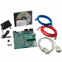
NNDK-MOD5272-KIT
Description
KIT DEVELOP NETWORK FOR MOD5272
Manufacturer
NetBurner Inc
Series
ColdFire®r
Datasheets
1.MOD5272-100IR.pdf
(2 pages)
2.MOD5272-100IR.pdf
(550 pages)
3.NNDK-MOD5282-KIT.pdf
(2 pages)
Specifications of NNDK-MOD5272-KIT
Main Purpose
*
Embedded
*
Utilized Ic / Part
MOD5272
Primary Attributes
*
Secondary Attributes
*
Processor To Be Evaluated
MOD5272
Interface Type
RS-232, RS-485, USB
Lead Free Status / RoHS Status
Contains lead / RoHS non-compliant
Lead Free Status / RoHS Status
Lead free / RoHS Compliant, Contains lead / RoHS non-compliant
Other names
528-1001


Address
MOTOROLA
14.5.2 QSPI Delay Register (QDLYR)
Figure 14-5 shows the QSPI delay register.
Table 14-4 gives QDLYR field descriptions.
Reset
Field
R/W
14–8
Bits
7–0
QSPI_Dout
15
QSPI_CLK
QSPI_Din
QSPI_CS
SPE
Name
15
QCD
SPE
DTL
QMR[CPOL] = 0
QMR[CPHA] = 1
QCR[CONT] = 0
14
Figure 14-4. QSPI Clocking and Data Transfer Example
QSPI enable. When set, the QSPI initiates transfers in master mode by executing commands in
the command RAM. Automatically cleared by the QSPI when a transfer completes.The user can
also clear this bit to abort transfer unless QIR[ABRTL] is set. The recommended method for
aborting transfers is to set QWR[HALT].
QSPILCK Delay. When the DSCK bit in the command RAM, is set this field determines the length
of the delay from assertion of the chip selects to valid QSPI_CLK transition.
Delay after transfer.When the DT bit in the command RAM sets this field determines the length of
delay after the serial transfer.
msb
15
15
Chapter 14. Queued Serial Peripheral Interface (QSPI) Module
A
14
14
Figure 14-5. QSPI Delay Register (QDLYR)
Table 14-4. QDLYR Field Descriptions
13
13
12
12
QCD
11
11
10
10
0000_0100_0000_0100
9
9
MBAR + 0x00A4
8
8
R/W
Description
8
7
7
7
6
6
Chip selects are active low
A = QDLYR[QCD]
B = QDLYR[DTL]
5
5
4
4
3
3
DTL
2
2
Programming Model
1
1
0
0
B
14-11
0
Related parts for NNDK-MOD5272-KIT
Image
Part Number
Description
Manufacturer
Datasheet
Request
R

Part Number:
Description:
BOARD SERIAL-ETHERNET 512K FLASH
Manufacturer:
NetBurner Inc
Datasheet:

Part Number:
Description:
PROCESSOR MODULE FLASH MOD5272
Manufacturer:
NetBurner Inc
Datasheet:

Part Number:
Description:
PROCESSOR MODULE 512KB FLASH
Manufacturer:
NetBurner Inc
Datasheet:

Part Number:
Description:
DUAL PORT SERIAL-ETHERNET
Manufacturer:
NetBurner Inc
Datasheet:

Part Number:
Description:
PROCESSOR MODULE FLASH
Manufacturer:
NetBurner Inc
Datasheet:

Part Number:
Description:
PROCESSOR MODULE 512KB FLASH
Manufacturer:
NetBurner Inc
Datasheet:

Part Number:
Description:
MOD5234 10/100 ETHERNET MODULE
Manufacturer:
NetBurner Inc
Datasheet:

Part Number:
Description:
KIT DEVELOP NETWORK FOR MOD5282
Manufacturer:
NetBurner Inc
Datasheet:

Part Number:
Description:
DUAL PORT SERIAL-ETHERNET
Manufacturer:
NetBurner Inc
Datasheet:

Part Number:
Description:
Ethernet Modules & Development Tools 32 Bit 66MHz 40 Pin DIP Industrial Temp
Manufacturer:
NetBurner Inc
Datasheet:

Part Number:
Description:
Ethernet Modules & Development Tools MOD5213 DEVELOPMENT KIT
Manufacturer:
NetBurner Inc

Part Number:
Description:
Ethernet Modules & Development Tools DUAL PORT SERIAL EHTERNET DEVICE
Manufacturer:
NetBurner Inc
Datasheet:

Part Number:
Description:
Ethernet ICs 32bit 147MHz CAN-to- Ethnt Device IndTemp
Manufacturer:
NetBurner Inc
Datasheet: