NNDK-MOD5272-KIT NetBurner Inc, NNDK-MOD5272-KIT Datasheet - Page 367
NNDK-MOD5272-KIT
Manufacturer Part Number
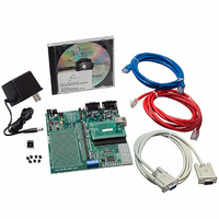
NNDK-MOD5272-KIT
Description
KIT DEVELOP NETWORK FOR MOD5272
Manufacturer
NetBurner Inc
Series
ColdFire®r
Datasheets
1.MOD5272-100IR.pdf
(2 pages)
2.MOD5272-100IR.pdf
(550 pages)
3.NNDK-MOD5282-KIT.pdf
(2 pages)
Specifications of NNDK-MOD5272-KIT
Main Purpose
*
Embedded
*
Utilized Ic / Part
MOD5272
Primary Attributes
*
Secondary Attributes
*
Processor To Be Evaluated
MOD5272
Interface Type
RS-232, RS-485, USB
Lead Free Status / RoHS Status
Contains lead / RoHS non-compliant
Lead Free Status / RoHS Status
Lead free / RoHS Compliant, Contains lead / RoHS non-compliant
Other names
528-1001


MOTOROLA
Bits
16.3.3 UART Status Registers (USRn)
The USRn, Figure 16-4, shows status of the transmitter, the receiver, and the FIFO.
7–6
3–0
5
4
Address
Reset
Field
R/W
TxRTS Transmitter ready-to-send. Controls negation of RTS to automatically terminate a message
TxCTS Transmitter clear-to-send. If both TxCTS and TxRTS are enabled, TxCTS controls the operation of the
Name
CM
SB
Channel mode. Selects a channel mode. Section 16.5.3, “Looping Modes,” describes individual
modes.
00 Normal
01 Automatic echo
10 Local loop-back
11 Remote loop-back
transmission when the transmitter is disabled after completion of a transmission. Attempting to
program a receiver and transmitter in the same channel for RTS control is not permitted and disables
RTS control for both.
0 The transmitter has no effect on RTS.
1 When the transmitter is disabled after transmission completes, setting this bit automatically clears
transmitter.
0 CTS has no effect on the transmitter.
1 Enables clear-to-send operation. The transmitter checks the state of CTS each time it is ready to
Stop-bit length control. Selects the length of the stop bit appended to the transmitted character.
Stop-bit lengths of 9/16th to 2 bits are programmable for 6–8 bit characters. Lengths of 1 1/16th to 2
bits are programmable for 5-bit characters. In all cases, the receiver checks only for a high condition at
the center of the first stop-bit position, that is, one bit time after the last data bit or after the parity bit, if
parity is enabled. If an external 1x clock is used for the transmitter, clearing bit 3 selects one stop bit
and setting bit 3 selects 2 stop bits for transmission.
RB
7
UOP[RTS] one bit time after any characters in the channel transmitter shift and holding registers are
completely sent, including the programmed number of stop bits.
send a character. If CTS is asserted, the character is sent; if it is negated, the channel TxD remains
in the high state and transmission is delayed until CTS is asserted. Changes in CTS as a character is
being sent do not affect its transmission.
0000 1.063
0001 1.125
0010 1.188
0011 1.250
SB
5 Bits
Figure 16-4. UART Status Registers (USRn)
FE
6
Table 16-3. UMR2n Field Descriptions
6–8 Bits
0.563
0.625
0.688
0.750
Chapter 16. UART Modules
PE
5
MBAR + 0x104 (USR0), 0x144 (USR1)
0100
0101
0110
0111
SB
5 Bits
1.313
1.375
1.438
1.500
OE
4
0000_0000
Read only
Description
6–8 Bits
0.813
0.875
0.938
1.000
TxEMP
3
1000
1001
1010
1011
SB
TxRDY
2
5–8 Bits
1.563
1.625
1.688
1.750
Register Descriptions
FFULL
1100
1101
1110
1111
1
SB
5–8 Bits
1.813
1.875
1.938
2.000
RxRDY
0
16-7
Related parts for NNDK-MOD5272-KIT
Image
Part Number
Description
Manufacturer
Datasheet
Request
R

Part Number:
Description:
BOARD SERIAL-ETHERNET 512K FLASH
Manufacturer:
NetBurner Inc
Datasheet:

Part Number:
Description:
PROCESSOR MODULE FLASH MOD5272
Manufacturer:
NetBurner Inc
Datasheet:

Part Number:
Description:
PROCESSOR MODULE 512KB FLASH
Manufacturer:
NetBurner Inc
Datasheet:

Part Number:
Description:
DUAL PORT SERIAL-ETHERNET
Manufacturer:
NetBurner Inc
Datasheet:

Part Number:
Description:
PROCESSOR MODULE FLASH
Manufacturer:
NetBurner Inc
Datasheet:

Part Number:
Description:
PROCESSOR MODULE 512KB FLASH
Manufacturer:
NetBurner Inc
Datasheet:

Part Number:
Description:
MOD5234 10/100 ETHERNET MODULE
Manufacturer:
NetBurner Inc
Datasheet:

Part Number:
Description:
KIT DEVELOP NETWORK FOR MOD5282
Manufacturer:
NetBurner Inc
Datasheet:

Part Number:
Description:
DUAL PORT SERIAL-ETHERNET
Manufacturer:
NetBurner Inc
Datasheet:

Part Number:
Description:
Ethernet Modules & Development Tools 32 Bit 66MHz 40 Pin DIP Industrial Temp
Manufacturer:
NetBurner Inc
Datasheet:

Part Number:
Description:
Ethernet Modules & Development Tools MOD5213 DEVELOPMENT KIT
Manufacturer:
NetBurner Inc

Part Number:
Description:
Ethernet Modules & Development Tools DUAL PORT SERIAL EHTERNET DEVICE
Manufacturer:
NetBurner Inc
Datasheet:

Part Number:
Description:
Ethernet ICs 32bit 147MHz CAN-to- Ethnt Device IndTemp
Manufacturer:
NetBurner Inc
Datasheet: