NNDK-MOD5272-KIT NetBurner Inc, NNDK-MOD5272-KIT Datasheet - Page 316
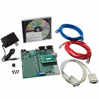
NNDK-MOD5272-KIT
Manufacturer Part Number
NNDK-MOD5272-KIT
Description
KIT DEVELOP NETWORK FOR MOD5272
Manufacturer
NetBurner Inc
Series
ColdFire®r
Datasheets
1.MOD5272-100IR.pdf
(2 pages)
2.MOD5272-100IR.pdf
(550 pages)
3.NNDK-MOD5282-KIT.pdf
(2 pages)
Specifications of NNDK-MOD5272-KIT
Main Purpose
*
Embedded
*
Utilized Ic / Part
MOD5272
Primary Attributes
*
Secondary Attributes
*
Processor To Be Evaluated
MOD5272
Interface Type
RS-232, RS-485, USB
Lead Free Status / RoHS Status
Contains lead / RoHS non-compliant
Lead Free Status / RoHS Status
Lead free / RoHS Compliant, Contains lead / RoHS non-compliant
Other names
528-1001


PLIC Registers
13.5.8 Loopback Control Register (PLCR)
All bits in this register are cleared on hardware or software reset.
The PLCR is an 8-bit register containing the configuration information for all four ports on
the MCF5272.
13-20
Bits
8
7
3
2
0
1
Name
SHB2
SHB1
ENB2
ENB1
DMX
ACT
Reset
Field
GCI Activation.
0 Default reset value.
1 Causes Dout to transition to a logic low for the respective port. This bit is only operational when
the port is in GCI mode. Setting the ACT bit in any other mode has no effect. It is the responsibility
of the CPU to clear the ACT bit when normal operation on Dout is required. This bit is intended to
be used to request activation from the upstream DCL/FSC driver. Periodic interrupts commence as
soon as the upstream device generates DCL, provided the appropriate interrupts, such as IE,
B1RIE, and so on, are enabled for the port.
Data multiplex.
0 port 3 Dout and Din are multiplexed onto Dout1 and Din1.
1 enables port 3 Dout and Din to be connected to dedicated output and input pins, DOUT3 and
B2 channel shift direction.
0 B2 channel data is received/transmitted msb first. The msb-first convention is often used for
1 B2 channel data is received/transmitted lsb first. The lsb-first convention is used when the data is
B1 channel shift direction. See SHB2.
Enable B2 data channel.
0 The B2 channel is disabled and all periodic interrupts in both receive and transmit directions are
1 Enables the B2 data channel for the respective port.
Enable B1 data channel. See ENB2.
Addr
Table 13-2. P0CR–P3CR Field Descriptions (Continued)
R/W
DIN3.
communication with PCM CODECs and converters.
to be HDLC encoded.
disabled. The behavior of Din and Dout in this state is shown below.
Figure 13-20. Loopback Control Register (PLCR)
7
Mode
GCI
IDL
LM3
6
All 1s
Operational (data on
Din visible)
MCF5272 User’s Manual
5
Din
LM2
MBAR + 0x38F
0000_0000
Read/Write
4
Description
High Impedance
Open drain
3
LM1
Dout
2
1
LM0
0
MOTOROLA
Related parts for NNDK-MOD5272-KIT
Image
Part Number
Description
Manufacturer
Datasheet
Request
R

Part Number:
Description:
BOARD SERIAL-ETHERNET 512K FLASH
Manufacturer:
NetBurner Inc
Datasheet:

Part Number:
Description:
PROCESSOR MODULE FLASH MOD5272
Manufacturer:
NetBurner Inc
Datasheet:

Part Number:
Description:
PROCESSOR MODULE 512KB FLASH
Manufacturer:
NetBurner Inc
Datasheet:

Part Number:
Description:
DUAL PORT SERIAL-ETHERNET
Manufacturer:
NetBurner Inc
Datasheet:

Part Number:
Description:
PROCESSOR MODULE FLASH
Manufacturer:
NetBurner Inc
Datasheet:

Part Number:
Description:
PROCESSOR MODULE 512KB FLASH
Manufacturer:
NetBurner Inc
Datasheet:

Part Number:
Description:
MOD5234 10/100 ETHERNET MODULE
Manufacturer:
NetBurner Inc
Datasheet:

Part Number:
Description:
KIT DEVELOP NETWORK FOR MOD5282
Manufacturer:
NetBurner Inc
Datasheet:

Part Number:
Description:
DUAL PORT SERIAL-ETHERNET
Manufacturer:
NetBurner Inc
Datasheet:

Part Number:
Description:
Ethernet Modules & Development Tools 32 Bit 66MHz 40 Pin DIP Industrial Temp
Manufacturer:
NetBurner Inc
Datasheet:

Part Number:
Description:
Ethernet Modules & Development Tools MOD5213 DEVELOPMENT KIT
Manufacturer:
NetBurner Inc

Part Number:
Description:
Ethernet Modules & Development Tools DUAL PORT SERIAL EHTERNET DEVICE
Manufacturer:
NetBurner Inc
Datasheet:

Part Number:
Description:
Ethernet ICs 32bit 147MHz CAN-to- Ethnt Device IndTemp
Manufacturer:
NetBurner Inc
Datasheet: