NNDK-MOD5272-KIT NetBurner Inc, NNDK-MOD5272-KIT Datasheet - Page 345
NNDK-MOD5272-KIT
Manufacturer Part Number
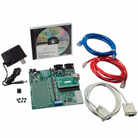
NNDK-MOD5272-KIT
Description
KIT DEVELOP NETWORK FOR MOD5272
Manufacturer
NetBurner Inc
Series
ColdFire®r
Datasheets
1.MOD5272-100IR.pdf
(2 pages)
2.MOD5272-100IR.pdf
(550 pages)
3.NNDK-MOD5282-KIT.pdf
(2 pages)
Specifications of NNDK-MOD5272-KIT
Main Purpose
*
Embedded
*
Utilized Ic / Part
MOD5272
Primary Attributes
*
Secondary Attributes
*
Processor To Be Evaluated
MOD5272
Interface Type
RS-232, RS-485, USB
Lead Free Status / RoHS Status
Contains lead / RoHS non-compliant
Lead Free Status / RoHS Status
Lead free / RoHS Compliant, Contains lead / RoHS non-compliant
Other names
528-1001


MOTOROLA
14.4.3 Transfer Delays
The QSPI supports programmable delays for the QSPI_CS signals before and after a
transfer. The time between QSPI_CS assertion and the leading QSPI_CLK edge, and the
time between the end of one transfer and the beginning of the next, are both independently
programmable.
The chip select to clock delay enable (DSCK) bit in command RAM, QCR[DSCK], enables
the programmable delay period from QSPI_CS assertion until the leading edge of
QSPI_CLK. QDLYR[QCD] determines the period of delay before the leading edge of
QSPI_CLK. The following expression determines the actual delay before the QSPI_CLK
leading edge:
QCD has a range of 1–127.
When QCD or DSCK equals zero, the standard delay of one-half the QSPI_CLK period is
used.
The delay after transmit enable (DT) bit in command RAM enables the programmable
delay period from the negation of the QSPI_CS signals until the start of the next transfer.
The delay after transfer can be used to provide a peripheral deselect interval. A delay can
also be inserted between consecutive transfers to allow serial A/D converters to complete
conversion. There are two transfer delay options: the user can choose to delay a standard
period after serial transfer is complete or can specify a delay period. Writing a value to
QDLYR[DTL] specifies a delay period. The DT bit in command RAM determines whether
the standard delay period (DT = 0) or the specified delay period (DT = 1) is used. The
following expression is used to calculate the delay:
where QDLYR[DTL] has a range of 1–255.
Table 14-2. QSPI_CLK Frequency as Function of CPU Clock and Baud Rate
Delay after transfer = 32 × QDLYR[DTL] /CLKIN frequency (DT = 1)
QMR [BAUD]
255
16
32
2
4
8
QSPI_CS-to-QSPI_CLK delay = QCD/CLKIN frequency
Chapter 14. Queued Serial Peripheral Interface (QSPI) Module
16,500,000
8,250,000
4,125,000
2,062,500
1,031,250
129,412
66 MHz
12,000,000
6,000,000
3,000,000
1,500,000
750,000
48 MHz
94,118
CPU Clock
8,250,000
4,125,000
2,062,500
1,031,250
515,625
33 MHz
64,706
5,000,000
2,500,000
1,250,000
625,000
312,500
20 MHz
39,216
Operation
14-7
Related parts for NNDK-MOD5272-KIT
Image
Part Number
Description
Manufacturer
Datasheet
Request
R

Part Number:
Description:
BOARD SERIAL-ETHERNET 512K FLASH
Manufacturer:
NetBurner Inc
Datasheet:

Part Number:
Description:
PROCESSOR MODULE FLASH MOD5272
Manufacturer:
NetBurner Inc
Datasheet:

Part Number:
Description:
PROCESSOR MODULE 512KB FLASH
Manufacturer:
NetBurner Inc
Datasheet:

Part Number:
Description:
DUAL PORT SERIAL-ETHERNET
Manufacturer:
NetBurner Inc
Datasheet:

Part Number:
Description:
PROCESSOR MODULE FLASH
Manufacturer:
NetBurner Inc
Datasheet:

Part Number:
Description:
PROCESSOR MODULE 512KB FLASH
Manufacturer:
NetBurner Inc
Datasheet:

Part Number:
Description:
MOD5234 10/100 ETHERNET MODULE
Manufacturer:
NetBurner Inc
Datasheet:

Part Number:
Description:
KIT DEVELOP NETWORK FOR MOD5282
Manufacturer:
NetBurner Inc
Datasheet:

Part Number:
Description:
DUAL PORT SERIAL-ETHERNET
Manufacturer:
NetBurner Inc
Datasheet:

Part Number:
Description:
Ethernet Modules & Development Tools 32 Bit 66MHz 40 Pin DIP Industrial Temp
Manufacturer:
NetBurner Inc
Datasheet:

Part Number:
Description:
Ethernet Modules & Development Tools MOD5213 DEVELOPMENT KIT
Manufacturer:
NetBurner Inc

Part Number:
Description:
Ethernet Modules & Development Tools DUAL PORT SERIAL EHTERNET DEVICE
Manufacturer:
NetBurner Inc
Datasheet:

Part Number:
Description:
Ethernet ICs 32bit 147MHz CAN-to- Ethnt Device IndTemp
Manufacturer:
NetBurner Inc
Datasheet: