NNDK-MOD5272-KIT NetBurner Inc, NNDK-MOD5272-KIT Datasheet - Page 330
NNDK-MOD5272-KIT
Manufacturer Part Number
NNDK-MOD5272-KIT
Description
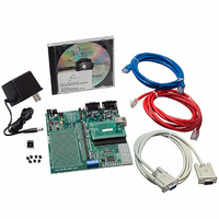
KIT DEVELOP NETWORK FOR MOD5272
Manufacturer
NetBurner Inc
Series
ColdFire®r
Datasheets
1.MOD5272-100IR.pdf
(2 pages)
2.MOD5272-100IR.pdf
(550 pages)
3.NNDK-MOD5282-KIT.pdf
(2 pages)
Specifications of NNDK-MOD5272-KIT
Main Purpose
*
Embedded
*
Utilized Ic / Part
MOD5272
Primary Attributes
*
Secondary Attributes
*
Processor To Be Evaluated
MOD5272
Interface Type
RS-232, RS-485, USB
Lead Free Status / RoHS Status
Contains lead / RoHS non-compliant
Lead Free Status / RoHS Status
Lead free / RoHS Compliant, Contains lead / RoHS non-compliant
Other names
528-1001


Application Examples
13.6.2 PLIC Initialization
The ports on the PLIC module of the MCF5272 require a number of registers to be
configured after power-on reset and prior to use. The following are the steps necessary for
initializing the ports.
The port configuration registers, PnCR, and the interrupt configuration register, PnICR,
must be initialized before using any port.
13.6.2.1 Port Configuration Example
The following example shows a basic configuration of port 1, assuming the following:
13-34
• Specify which ports are active.
• Specify the operational modes, IDL8, IDL10, and so on, for the active ports,
• If GCI mode is specified in PnCR[M], select whether GCI SCIT mode is to be used,
• If port 1 is used, program whether the 2-KHz frame interrupt is to be derived from
• If port 1 is used, program whether it receives as inputs DCL and FSC or whether it
• If the port is in GCI mode, the PnCR[ACT] bit may be set if GCI Activation should
• If port 3 is used, program the PnCR[DMX] bit if this port is routed through physical
• Program the shift direction for the B1 and B2 channels, PnCR[SHB1–SHB2], to
• Program PnCR[ENB1–ENB2] to specify whether B1 or B2 is enabled at
• port 1 is active as slave using IDL10 mode
• 2-KHz frame interrupt derived from port 1
• msb first on B1 and B2
• B1 and B2 disabled.
PnCR[M].
PnCR[G/S]
port 0 or port 1, PnCR[FSM].
drives these signals as outputs.
be requested.
interface 3 (DIN3/DOUT3).
specify msb or lsb first.
initialization.
MCF5272 User’s Manual
MOTOROLA
Related parts for NNDK-MOD5272-KIT
Image
Part Number
Description
Manufacturer
Datasheet
Request
R

Part Number:
Description:
BOARD SERIAL-ETHERNET 512K FLASH
Manufacturer:
NetBurner Inc
Datasheet:

Part Number:
Description:
PROCESSOR MODULE FLASH MOD5272
Manufacturer:
NetBurner Inc
Datasheet:

Part Number:
Description:
PROCESSOR MODULE 512KB FLASH
Manufacturer:
NetBurner Inc
Datasheet:

Part Number:
Description:
DUAL PORT SERIAL-ETHERNET
Manufacturer:
NetBurner Inc
Datasheet:

Part Number:
Description:
PROCESSOR MODULE FLASH
Manufacturer:
NetBurner Inc
Datasheet:

Part Number:
Description:
PROCESSOR MODULE 512KB FLASH
Manufacturer:
NetBurner Inc
Datasheet:

Part Number:
Description:
MOD5234 10/100 ETHERNET MODULE
Manufacturer:
NetBurner Inc
Datasheet:

Part Number:
Description:
KIT DEVELOP NETWORK FOR MOD5282
Manufacturer:
NetBurner Inc
Datasheet:

Part Number:
Description:
DUAL PORT SERIAL-ETHERNET
Manufacturer:
NetBurner Inc
Datasheet:

Part Number:
Description:
Ethernet Modules & Development Tools 32 Bit 66MHz 40 Pin DIP Industrial Temp
Manufacturer:
NetBurner Inc
Datasheet:

Part Number:
Description:
Ethernet Modules & Development Tools MOD5213 DEVELOPMENT KIT
Manufacturer:
NetBurner Inc

Part Number:
Description:
Ethernet Modules & Development Tools DUAL PORT SERIAL EHTERNET DEVICE
Manufacturer:
NetBurner Inc
Datasheet:

Part Number:
Description:
Ethernet ICs 32bit 147MHz CAN-to- Ethnt Device IndTemp
Manufacturer:
NetBurner Inc
Datasheet: