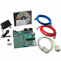
NNDK-MOD5272-KIT NetBurner Inc, NNDK-MOD5272-KIT Datasheet - Page 478

NNDK-MOD5272-KIT
Manufacturer Part Number
NNDK-MOD5272-KIT
Description
KIT DEVELOP NETWORK FOR MOD5272
Manufacturer
NetBurner Inc
Series
ColdFire®r
Datasheets
1.MOD5272-100IR.pdf
(2 pages)
2.MOD5272-100IR.pdf
(550 pages)
3.NNDK-MOD5282-KIT.pdf
(2 pages)
Specifications of NNDK-MOD5272-KIT
Main Purpose
*
Embedded
*
Utilized Ic / Part
MOD5272
Primary Attributes
*
Secondary Attributes
*
Processor To Be Evaluated
MOD5272
Interface Type
RS-232, RS-485, USB
Lead Free Status / RoHS Status
Contains lead / RoHS non-compliant
Lead Free Status / RoHS Status
Lead free / RoHS Compliant, Contains lead / RoHS non-compliant
Other names
528-1001
- Current page: 478 of 550
- Download datasheet (6Mb)
Reset Operation
The levels of the mode select inputs, QSPI_Dout/WSEL, QSPI_CLK/BUSW1, and
QSPI_CS0/BUSW0, are sampled when RSTI negates and select the port size of CS0 and
the physical data bus width after a master reset occurs. The INTx signals are synchronized
and are registered on the last falling edge of CLKIN where RSTI is asserted.
A master reset causes any bus cycle (including SDRAM refresh cycles) to terminate. In
addition, master reset initializes registers appropriately for a reset exception. During an
external master reset, SCR[RSTSRC] is set to 0b11 to indicate that assertion of RSTI and
DRESETEN caused the previous reset.
20.12.2 Normal Reset
External normal resets should be performed anytime it is important to maintain the data
stored in SDRAM during a reset. An external normal reset is performed when an external
device asserts RSTI while negating DRESETEN. At power on reset both RSTI and
DRESETEN must be asserted simultaneously. If DRESETEN is not asserted at the same
time as RSTI at power up the SDRAMC cannot be initialized by software.
During an external normal reset, RSTI must be asserted for a minimum of six CLKINs.
Figure 20-22 is a functional timing diagram of external normal reset operation, illustrating
relationships among RSTI, DRESETEN, RSTO, mode selects, and bus signals. RSTI and
DRESETEN are internally synchronized on consecutive falling and rising clocks before
being used and must meet the specified setup and hold times to the falling edge of CLKIN
only if recognition by a specific falling edge is required
The levels of the mode select inputs, QSPI_Dout/WSEL, QSPI_CLK/BUSW1,
QSPI_CS0/BUSW0, and HiZ are sampled when RSTO negates and select the port size of
CS0 and the physical data bus width after a master reset occurs. RSTO is asserted as long
20-24
.
CLKIN
VDD
RSTI
DRESETEN
Mode Select
Inputs
RSTO
BUS SIGNALS
(H)
Figure 20-22. Normal Reset Timing
MCF5272 User’s Manual
CLK CYCLES
T >= 6
CLK CYCLES
T = 32,768
CLK CYCLES
T >= 22
MOTOROLA
Related parts for NNDK-MOD5272-KIT
Image
Part Number
Description
Manufacturer
Datasheet
Request
R

Part Number:
Description:
BOARD SERIAL-ETHERNET 512K FLASH
Manufacturer:
NetBurner Inc
Datasheet:

Part Number:
Description:
PROCESSOR MODULE FLASH MOD5272
Manufacturer:
NetBurner Inc
Datasheet:

Part Number:
Description:
PROCESSOR MODULE 512KB FLASH
Manufacturer:
NetBurner Inc
Datasheet:

Part Number:
Description:
DUAL PORT SERIAL-ETHERNET
Manufacturer:
NetBurner Inc
Datasheet:

Part Number:
Description:
PROCESSOR MODULE FLASH
Manufacturer:
NetBurner Inc
Datasheet:

Part Number:
Description:
PROCESSOR MODULE 512KB FLASH
Manufacturer:
NetBurner Inc
Datasheet:

Part Number:
Description:
MOD5234 10/100 ETHERNET MODULE
Manufacturer:
NetBurner Inc
Datasheet:

Part Number:
Description:
KIT DEVELOP NETWORK FOR MOD5282
Manufacturer:
NetBurner Inc
Datasheet:

Part Number:
Description:
DUAL PORT SERIAL-ETHERNET
Manufacturer:
NetBurner Inc
Datasheet:

Part Number:
Description:
Ethernet Modules & Development Tools 32 Bit 66MHz 40 Pin DIP Industrial Temp
Manufacturer:
NetBurner Inc
Datasheet:

Part Number:
Description:
Ethernet Modules & Development Tools MOD5213 DEVELOPMENT KIT
Manufacturer:
NetBurner Inc

Part Number:
Description:
Ethernet Modules & Development Tools DUAL PORT SERIAL EHTERNET DEVICE
Manufacturer:
NetBurner Inc
Datasheet:

Part Number:
Description:
Ethernet ICs 32bit 147MHz CAN-to- Ethnt Device IndTemp
Manufacturer:
NetBurner Inc
Datasheet:


