NNDK-MOD5272-KIT NetBurner Inc, NNDK-MOD5272-KIT Datasheet - Page 347
NNDK-MOD5272-KIT
Manufacturer Part Number
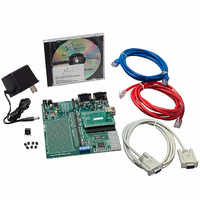
NNDK-MOD5272-KIT
Description
KIT DEVELOP NETWORK FOR MOD5272
Manufacturer
NetBurner Inc
Series
ColdFire®r
Datasheets
1.MOD5272-100IR.pdf
(2 pages)
2.MOD5272-100IR.pdf
(550 pages)
3.NNDK-MOD5282-KIT.pdf
(2 pages)
Specifications of NNDK-MOD5272-KIT
Main Purpose
*
Embedded
*
Utilized Ic / Part
MOD5272
Primary Attributes
*
Secondary Attributes
*
Processor To Be Evaluated
MOD5272
Interface Type
RS-232, RS-485, USB
Lead Free Status / RoHS Status
Contains lead / RoHS non-compliant
Lead Free Status / RoHS Status
Lead free / RoHS Compliant, Contains lead / RoHS non-compliant
Other names
528-1001


MOTOROLA
RAM. Each time the end of the queue is reached, QIR[SPIFE] is set. QIR[SPIF] is not
automatically reset. If interrupt driven QSPI service is used, the service routine must clear
QIR[SPIF] to abort the current request. Additional interrupt requests during servicing can
be prevented by clearing QIR[SPIFE].
There are two recommended methods of exiting wraparound mode: clearing
QWR[WREN] or setting QWR[HALT]. Exiting wraparound mode by clearing
QDLYR[SPE] is not recommended because this may abort a serial transfer in progress. The
QSPI sets SPIF, clears QDLYR[SPE], and stops the first time it reaches the end of the queue
after QWR[WREN] is cleared. After QWR[HALT] is set, the QSPI finishes the current
transfer, then stops executing commands. After the QSPI stops, QDLYR[SPE] can be
cleared.
14.5 Programming Model
The programming model for the QSPI consists of six registers. They are the QSPI mode
register (QMR), QSPI delay register (QDLYR), QSPI wrap register (QWR), QSPI interrupt
register (QIR), QSPI address register (QAR), and the QSPI data register (QDR).
There are a total of 80 bytes of memory used for transmit, receive, and control data. This
memory is accessed indirectly using QAR and QDR.
Registers and RAM are written and read by the CPU.
14.5.1 QSPI Mode Register (QMR)
The QMR register, shown in Figure 14-3, determines the basic operating modes of the
QSPI module. Parameters such as clock polarity and phase, baud rate, master mode
operation, and transfer size are determined by this register. The data output high impedance
enable, DOHIE, controls the operation of QSPI_Dout between data transfers. When
DOHIE is cleared, QSPI_Dout is actively driven between transfers. When DOHIE is set,
QSPI_Dout assumes a high impedance state.
Address
Reset
Field
R/W
MSTR DOHIE
15
Because the QSPI does not operate in slave mode, the master
mode enable bit, QMR[MSTR], must be set for the QSPI
module to operate correctly.
Chapter 14. Queued Serial Peripheral Interface (QSPI) Module
14
Figure 14-3. QSPI Mode Register (QMR)
13
BITS
10
0000_0001_0000_0100
NOTE:
CPOL CPHA
MBAR + 0x00A0
9
R/W
8
7
BAUD
Programming Model
14-9
0
Related parts for NNDK-MOD5272-KIT
Image
Part Number
Description
Manufacturer
Datasheet
Request
R

Part Number:
Description:
BOARD SERIAL-ETHERNET 512K FLASH
Manufacturer:
NetBurner Inc
Datasheet:

Part Number:
Description:
PROCESSOR MODULE FLASH MOD5272
Manufacturer:
NetBurner Inc
Datasheet:

Part Number:
Description:
PROCESSOR MODULE 512KB FLASH
Manufacturer:
NetBurner Inc
Datasheet:

Part Number:
Description:
DUAL PORT SERIAL-ETHERNET
Manufacturer:
NetBurner Inc
Datasheet:

Part Number:
Description:
PROCESSOR MODULE FLASH
Manufacturer:
NetBurner Inc
Datasheet:

Part Number:
Description:
PROCESSOR MODULE 512KB FLASH
Manufacturer:
NetBurner Inc
Datasheet:

Part Number:
Description:
MOD5234 10/100 ETHERNET MODULE
Manufacturer:
NetBurner Inc
Datasheet:

Part Number:
Description:
KIT DEVELOP NETWORK FOR MOD5282
Manufacturer:
NetBurner Inc
Datasheet:

Part Number:
Description:
DUAL PORT SERIAL-ETHERNET
Manufacturer:
NetBurner Inc
Datasheet:

Part Number:
Description:
Ethernet Modules & Development Tools 32 Bit 66MHz 40 Pin DIP Industrial Temp
Manufacturer:
NetBurner Inc
Datasheet:

Part Number:
Description:
Ethernet Modules & Development Tools MOD5213 DEVELOPMENT KIT
Manufacturer:
NetBurner Inc

Part Number:
Description:
Ethernet Modules & Development Tools DUAL PORT SERIAL EHTERNET DEVICE
Manufacturer:
NetBurner Inc
Datasheet:

Part Number:
Description:
Ethernet ICs 32bit 147MHz CAN-to- Ethnt Device IndTemp
Manufacturer:
NetBurner Inc
Datasheet: