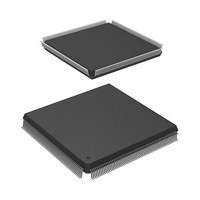
R5S72030W200FP Renesas Electronics America, R5S72030W200FP Datasheet - Page 355

R5S72030W200FP
Manufacturer Part Number
R5S72030W200FP
Description
IC SUPERH MPU ROMLESS 240QFP
Manufacturer
Renesas Electronics America
Series
SuperH® SH7200r
Specifications of R5S72030W200FP
Core Processor
SH2A-FPU
Core Size
32-Bit
Speed
200MHz
Connectivity
CAN, I²C, SCI, SSI, SSU, USB
Peripherals
DMA, LCD, POR, PWM, WDT
Number Of I /o
82
Program Memory Type
ROMless
Ram Size
80K x 8
Voltage - Supply (vcc/vdd)
1.1 V ~ 3.6 V
Data Converters
A/D 8x10b; D/A 2x8b
Oscillator Type
Internal
Operating Temperature
-20°C ~ 85°C
Package / Case
240-QFP
For Use With
R0K572030S000BE - KIT DEV FOR SH7203HS0005KCU11H - EMULATOR E10A-USB H8S(X),SH2(A)
Lead Free Status / RoHS Status
Contains lead / RoHS non-compliant
Eeprom Size
-
Program Memory Size
-
Available stocks
Company
Part Number
Manufacturer
Quantity
Price
Company:
Part Number:
R5S72030W200FP
Manufacturer:
SAMSUNG
Quantity:
1 001
Company:
Part Number:
R5S72030W200FP
Manufacturer:
Renesas Electronics America
Quantity:
10 000
- Current page: 355 of 503
- Download datasheet (3Mb)
8.2
The interval during which one stage is executed is called a slot. The following rules apply to a
slot.
(1) Each stage of an instruction (IF, ID, EX, MA, WB, mm, E1, E2, DF, ED, SF, NA) is always
(2) The maximum number of different stages of different instructions set in one slot is two in the
(3) The number of states (number of system clock cycles) S required for execution of one slot is
Instruction 1
Instruction 2
Note: ID and EX of instruction 1 are executed in one slot.
Instruction 1
Instruction 2
Instruction 3
Note: Three ID stages are executed in one slot.
executed in one slot. Two or more stages are never executed in one slot (see figure 8.3). The
ED stage operates without regard to a slot.
case of integer pipelines, and one in the case of other pipelines. Simultaneous pipeline
execution never exceeds this number (see figure 8.4).
calculated using the following conditions.
(a) S = (maximum number of states among stages of each instruction contained in one slot)
(b) The number of execution states of each stage is as follows:
That is to say, instructions that have other short stages are stalled by the longest stage.
• IF:
• ID:
• EX:
X
Slots and Pipeline Flow
Number of memory access clocks for instruction fetch
(As a fetch buffer is provided and instruction fetches are performed beforehand,
pipeline stalling only occurs when a fetched instruction must be decoded
immediately.)
Always 1 state
Always 1 state
IF
IF
IF
↔ ←
IF
ID
ID
ID
ID
IF
Figure 8.3 Impossible Pipeline Flow (1)
Figure 8.4 Impossible Pipeline Flow (2)
EX
EX
EX
→ ↔ ↔ ↔ ↔ ↔ ↔ ↔ : Slots
EX
MA
MA
ID
WB
WB
EX
MA
WB
Rev. 3.00 Jul 08, 2005 page 339 of 484
Section 8 Pipeline Operation
REJ09B0051-0300
Related parts for R5S72030W200FP
Image
Part Number
Description
Manufacturer
Datasheet
Request
R

Part Number:
Description:
KIT STARTER FOR M16C/29
Manufacturer:
Renesas Electronics America
Datasheet:

Part Number:
Description:
KIT STARTER FOR R8C/2D
Manufacturer:
Renesas Electronics America
Datasheet:

Part Number:
Description:
R0K33062P STARTER KIT
Manufacturer:
Renesas Electronics America
Datasheet:

Part Number:
Description:
KIT STARTER FOR R8C/23 E8A
Manufacturer:
Renesas Electronics America
Datasheet:

Part Number:
Description:
KIT STARTER FOR R8C/25
Manufacturer:
Renesas Electronics America
Datasheet:

Part Number:
Description:
KIT STARTER H8S2456 SHARPE DSPLY
Manufacturer:
Renesas Electronics America
Datasheet:

Part Number:
Description:
KIT STARTER FOR R8C38C
Manufacturer:
Renesas Electronics America
Datasheet:

Part Number:
Description:
KIT STARTER FOR R8C35C
Manufacturer:
Renesas Electronics America
Datasheet:

Part Number:
Description:
KIT STARTER FOR R8CL3AC+LCD APPS
Manufacturer:
Renesas Electronics America
Datasheet:

Part Number:
Description:
KIT STARTER FOR RX610
Manufacturer:
Renesas Electronics America
Datasheet:

Part Number:
Description:
KIT STARTER FOR R32C/118
Manufacturer:
Renesas Electronics America
Datasheet:

Part Number:
Description:
KIT DEV RSK-R8C/26-29
Manufacturer:
Renesas Electronics America
Datasheet:

Part Number:
Description:
KIT STARTER FOR SH7124
Manufacturer:
Renesas Electronics America
Datasheet:

Part Number:
Description:
KIT STARTER FOR H8SX/1622
Manufacturer:
Renesas Electronics America
Datasheet:

Part Number:
Description:
KIT DEV FOR SH7203
Manufacturer:
Renesas Electronics America
Datasheet:


