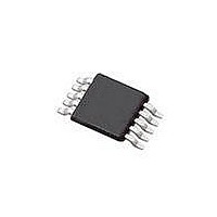
SI4010-C2-GT Silicon Laboratories Inc, SI4010-C2-GT Datasheet - Page 101

SI4010-C2-GT
Manufacturer Part Number
SI4010-C2-GT
Description
IC TX 27-960MHZ FSK 3.6V 10MSOP
Manufacturer
Silicon Laboratories Inc
Series
EZRadio®r
Type
Crystalless SoC RF Transmitterr
Datasheet
1.SI4010-C2-GT.pdf
(156 pages)
Specifications of SI4010-C2-GT
Package / Case
10-MSOP
Mfg Application Notes
SI4010 Calculator Spreadsheet AppNote
Frequency
27MHz ~ 960MHz
Applications
Garage Openers, RKE, Security Alarms
Modulation Or Protocol
FSK, OOK
Data Rate - Maximum
100 kBaud
Power - Output
10dBm
Current - Transmitting
19.8mA
Data Interface
PCB, Surface Mount
Antenna Connector
PCB, Surface Mount
Memory Size
4kB RAM
Features
8051 MCU Core, Crystal-less Operation
Voltage - Supply
1.8 V ~ 3.6 V
Operating Temperature
-40°C ~ 85°C
Operating Frequency
27 MHz to 960 MHz
Maximum Operating Temperature
+ 85 C
Mounting Style
SMD/SMT
Operating Supply Voltage
1.8 V to 3.6 V
Supply Current
14.2 mA
Lead Free Status / RoHS Status
Lead free / RoHS Compliant
Lead Free Status / RoHS Status
Lead free / RoHS Compliant, Lead free / RoHS Compliant
Other names
336-1997-5
Available stocks
Company
Part Number
Manufacturer
Quantity
Price
Part Number:
SI4010-C2-GT
Manufacturer:
SILICON LABS/èٹ¯ç§‘
Quantity:
20 000
Company:
Part Number:
SI4010-C2-GTR
Manufacturer:
ST
Quantity:
1 000
Part Number:
SI4010-C2-GTR
Manufacturer:
SILICON LABS/èٹ¯ç§‘
Quantity:
20 000
27. Power Management Modes
The CIP-51 core has two software programmable power management modes: Idle and Stop. Idle mode
halts the CPU while leaving the external peripherals and internal clocks active. In Stop mode, the CPU is
halted, all interrupts and timers are inactive. The system clock is still running when the CPU is in Stop
mode. Since clocks are running, power consumption is dependent upon the system clock frequency and
the number of peripherals left in active mode before entering Idle or Stop. See the SFR definition of the
Power Control Register (PCON) used to control the CPU power management modes.
Although the CIP-51 has Idle and Stop modes built in (as with any standard 8051 architecture), power
management of the entire MCU is better accomplished by enabling/disabling individual peripherals as
needed. Each analog peripheral can be disabled when not in use and put into low power mode. Digital
peripherals, such as timers, draw little power whenever they are not in use.
The devices feature an additional shutdown mode, which shuts the device down. The device then can be
woken up by pulling GPIO input to ground. See other sections for details.
27.1. Idle Mode
Setting the Idle Mode Select bit (PCON.0) causes the CIP-51 to halt the CPU and enter Idle mode as soon
as the instruction that sets the bit completes. All internal registers and memory maintain their original data.
All analog and digital peripherals can remain active during Idle mode.
Idle mode is terminated when an enabled interrupt or reset is asserted. The assertion of an enabled inter-
rupt will cause the Idle Mode Selection bit (PCON.0) to be cleared and the CPU to resume operation. The
pending interrupt will be serviced and the next instruction to be executed after the return from interrupt
(RETI) will be the instruction immediately following the one that set the Idle Mode Select bit. If Idle mode is
terminated by an external reset, the CIP-51 performs a normal reset sequence.
Note: Any instruction which sets the IDLE bit should be immediately followed by an instruction which has two or more
In C:
In assembly:
If the instruction following the write to the IDLE bit is a single-byte instruction and an interrupt occurs during
the execution of the instruction of the instruction which sets the IDLE bit, the CPU may not wake from IDLE
mode when a future interrupt occurs.
27.2. Stop Mode
Setting the Stop Mode Select bit (PCON.1) causes the CIP-51 to enter Stop mode as soon as the instruc-
tion that sets the bit completes. In Stop mode, the CPU is stopped, effectively shutting down all digital
peripherals. Each analog peripheral must be shut down individually prior to entering Stop mode. Stop
mode can only be terminated by an external reset. On reset, the CIP-51 performs the normal reset
sequence and begins program execution based on the program level of the chip.
The system clock is not stopped when in Stop mode.
opcode bytes. For example:
PCON |= 0x01; // Set IDLE bit
PCON = PCON; // ... Followed by a 3-cycle Dummy Instruction;
ORL PCON, #01h ; Set IDLE bit
MOV PCON, PCON ; ... Followed by a 3-cycle Dummy Instruction
Rev. 1.0
Si4010-C2
101


