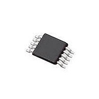
SI4010-C2-GT Silicon Laboratories Inc, SI4010-C2-GT Datasheet - Page 114

SI4010-C2-GT
Manufacturer Part Number
SI4010-C2-GT
Description
IC TX 27-960MHZ FSK 3.6V 10MSOP
Manufacturer
Silicon Laboratories Inc
Series
EZRadio®r
Type
Crystalless SoC RF Transmitterr
Datasheet
1.SI4010-C2-GT.pdf
(156 pages)
Specifications of SI4010-C2-GT
Package / Case
10-MSOP
Mfg Application Notes
SI4010 Calculator Spreadsheet AppNote
Frequency
27MHz ~ 960MHz
Applications
Garage Openers, RKE, Security Alarms
Modulation Or Protocol
FSK, OOK
Data Rate - Maximum
100 kBaud
Power - Output
10dBm
Current - Transmitting
19.8mA
Data Interface
PCB, Surface Mount
Antenna Connector
PCB, Surface Mount
Memory Size
4kB RAM
Features
8051 MCU Core, Crystal-less Operation
Voltage - Supply
1.8 V ~ 3.6 V
Operating Temperature
-40°C ~ 85°C
Operating Frequency
27 MHz to 960 MHz
Maximum Operating Temperature
+ 85 C
Mounting Style
SMD/SMT
Operating Supply Voltage
1.8 V to 3.6 V
Supply Current
14.2 mA
Lead Free Status / RoHS Status
Lead free / RoHS Compliant
Lead Free Status / RoHS Status
Lead free / RoHS Compliant, Lead free / RoHS Compliant
Other names
336-1997-5
Available stocks
Company
Part Number
Manufacturer
Quantity
Price
Part Number:
SI4010-C2-GT
Manufacturer:
SILICON LABS/èٹ¯ç§‘
Quantity:
20 000
Company:
Part Number:
SI4010-C2-GTR
Manufacturer:
ST
Quantity:
1 000
Part Number:
SI4010-C2-GTR
Manufacturer:
SILICON LABS/èٹ¯ç§‘
Quantity:
20 000
Si4010-C2
30.4. Pullup Roff and Matrix Mode Option Control
Both Roff and Matrix mode options are controlled by the GPIO pad itself. The control is implemented as 2
bit latch inside of the GPIO pads. Both options stay in their used defined states during chip shutdown. In
other words, if the chip is in shutdown mode, the digital logic does not have power, but the two GPIO
latches keep the user set values of those options.
The options are controlled by the PORT_CTRL SFR register. The user has to strobe the desired values to
the GPIO latches by software sequence. The latch enable is a PORT_STROBE bit in the PORT_CTRL
register.
For example, to disable the both Matrix and Roff options at the beginning of use application, the user code
should look like this in assembly:
Using Silicon Labs provided masks in the header:
The toggle of the PORT_STROBE from 0 to 1 back to 0 latches the current register values of
PORT_MATRIX and PORT_ROFF.
To summarize: To change the values of the Matrix an Roff options, the following software sequence is
required:
1. Set the desired values of PORT_MATRIX and PORT_ROFF bits in the PORT_CTRL register.
2. Toggle the PORT_STROBE bit in the PORT_CTRL register from 0 to 1 back to 0 while not changing
3. Note that while reading the PORT_CTRL the current value of the Matrix and Roff options is read from
Invoking a Matrix mode requires the following sequence:
1. Set the GPIO[3:1] as inputs, which means writing 1 to the port value and making the driver open drain.
2. Latch PORT_MATRIX=1 and PROT_ROFF=0 values to the GPIO option control latch.
114
any other bit in the PORT_CTRL register. The new Matrix and Roff control values are latched into the
GPIO.
the GPIO, not the value of the write register for the new Matrix and Roff setting.
anl PORT_CTRL, #10011111B
orl PORT_CTRL, #10000000B
anl PORT_CTRL, #01111111B
anl PORT_CTRL, #NOT(M_PORT_MATRIX OR M_PORT_ROFF)
orl PORT_CTRL, #M_PORT_STROBE
anl PORT_CTRL, #NOT(M_PORT_STROBE)
; Clear PORT_MATRIX and PORT_ROFF
; Set PORT_STROBE=1
; Clear PORT_STROBE=0
Rev. 1.0


