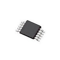
SI4010-C2-GT Silicon Laboratories Inc, SI4010-C2-GT Datasheet - Page 131

SI4010-C2-GT
Manufacturer Part Number
SI4010-C2-GT
Description
IC TX 27-960MHZ FSK 3.6V 10MSOP
Manufacturer
Silicon Laboratories Inc
Series
EZRadio®r
Type
Crystalless SoC RF Transmitterr
Datasheet
1.SI4010-C2-GT.pdf
(156 pages)
Specifications of SI4010-C2-GT
Package / Case
10-MSOP
Mfg Application Notes
SI4010 Calculator Spreadsheet AppNote
Frequency
27MHz ~ 960MHz
Applications
Garage Openers, RKE, Security Alarms
Modulation Or Protocol
FSK, OOK
Data Rate - Maximum
100 kBaud
Power - Output
10dBm
Current - Transmitting
19.8mA
Data Interface
PCB, Surface Mount
Antenna Connector
PCB, Surface Mount
Memory Size
4kB RAM
Features
8051 MCU Core, Crystal-less Operation
Voltage - Supply
1.8 V ~ 3.6 V
Operating Temperature
-40°C ~ 85°C
Operating Frequency
27 MHz to 960 MHz
Maximum Operating Temperature
+ 85 C
Mounting Style
SMD/SMT
Operating Supply Voltage
1.8 V to 3.6 V
Supply Current
14.2 mA
Lead Free Status / RoHS Status
Lead free / RoHS Compliant
Lead Free Status / RoHS Status
Lead free / RoHS Compliant, Lead free / RoHS Compliant
Other names
336-1997-5
Available stocks
Company
Part Number
Manufacturer
Quantity
Price
Part Number:
SI4010-C2-GT
Manufacturer:
SILICON LABS/èٹ¯ç§‘
Quantity:
20 000
Company:
Part Number:
SI4010-C2-GTR
Manufacturer:
ST
Quantity:
1 000
Part Number:
SI4010-C2-GTR
Manufacturer:
SILICON LABS/èٹ¯ç§‘
Quantity:
20 000
34. Timers 2 and 3
The Si4010 device includes two identical timers, Timer 2 (TMR2) and Timer 3 (TMR3). Since the timers are
identical, the description will refer to Timer 2 (TMR2). The reader can replace the TMR2 with TMR3 in the
text to get the description of Timer 3 (TMR3). The description refers to a “Timer” as an alias for either
TMR2 or TMR3.
Timer 2 is a 16-bit timer formed by two 8-bit SFRs: TMR2L (low byte) and TMR2H (high byte). Timer may
operate in on of the two width modes:
In each of the width modes each timer or each half of the timer can operate in two different functional
modes:
Each timer or timer half can be independently clocked from one of 4 clock sources. Clock source can be
independently set for each half of the timer in split mode. The clock sources available for each timer half
are:
1. Current system clock clk_sys. This is 24MHz, possibly divided by N-th power of 2 with N=0, ..., 7. See
2. Current system clock clk_sys divided by 12 .. clk_sys/12
3. RTC timer tick rtc_tick with 5.33us period (24MHz/128)
4. RTC timer 100us pulse. See the RTC section for an important note related to the uniformity of the
All clock sources are synchronous with the system clock.
The capture event is INT0 for TMR2 and INT1 for TMR3. They are edge events coming from external
GPIO and are the same as for the external interrupt generation, INT0 and INT1. To use these events as
capture events they have to be programmed exactly the same way as if they were intended to be used for
interrupt generation. They could generate INT0 and INT1 interrupts at the same time when the are being
used as capture events for TMR2 and TMR3, respectively.
If the timer operates in split mode both halves are completely independent. Therefore, all 4 combinations
of functionality in split mode, timer/timer, timer/capture, capture/timer, and capture/capture are possible.
Each half has separate clock selection. The only common thing is the capture signal, which is the same for
both halves in split mode. The only difference in between of two halves in capture/capture mode can be
the counter clock, set independently for each half.
Wide mode .. timer operates as a single 16 bit wide timer controlled by the control bits related to the low
half of the timer, like TMR2L_MODE, etc. The timer sets the TMR2INTH bit as an interrupt flag.
Split mode .. timer operates as two independent 8 bit wide times, with related control bits related to
high (H) and low (L) half of the overall 16 bit timer.
Timer mode .. the timer runs as a counter counting up, when it overflows it sets corresponding interrupt
flag, reloads initial value, and keeps going, counting up.
Capture mode .. the timer counter is free running counting up. When it overflows it keeps counting up
from 0. When an external capture event happens then the current value of the timer is captured in the
capture register, the counter keeps counting and will not stop. The interrupt flag is set by the capture
event.
SYSGEN SFR register for system clock setting details.
100us pulse train.
Rev. 1.0
Si4010-C2
131


