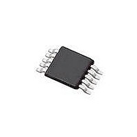
SI4010-C2-GT Silicon Laboratories Inc, SI4010-C2-GT Datasheet - Page 152

SI4010-C2-GT
Manufacturer Part Number
SI4010-C2-GT
Description
IC TX 27-960MHZ FSK 3.6V 10MSOP
Manufacturer
Silicon Laboratories Inc
Series
EZRadio®r
Type
Crystalless SoC RF Transmitterr
Datasheet
1.SI4010-C2-GT.pdf
(156 pages)
Specifications of SI4010-C2-GT
Package / Case
10-MSOP
Mfg Application Notes
SI4010 Calculator Spreadsheet AppNote
Frequency
27MHz ~ 960MHz
Applications
Garage Openers, RKE, Security Alarms
Modulation Or Protocol
FSK, OOK
Data Rate - Maximum
100 kBaud
Power - Output
10dBm
Current - Transmitting
19.8mA
Data Interface
PCB, Surface Mount
Antenna Connector
PCB, Surface Mount
Memory Size
4kB RAM
Features
8051 MCU Core, Crystal-less Operation
Voltage - Supply
1.8 V ~ 3.6 V
Operating Temperature
-40°C ~ 85°C
Operating Frequency
27 MHz to 960 MHz
Maximum Operating Temperature
+ 85 C
Mounting Style
SMD/SMT
Operating Supply Voltage
1.8 V to 3.6 V
Supply Current
14.2 mA
Lead Free Status / RoHS Status
Lead free / RoHS Compliant
Lead Free Status / RoHS Status
Lead free / RoHS Compliant, Lead free / RoHS Compliant
Other names
336-1997-5
Available stocks
Company
Part Number
Manufacturer
Quantity
Price
Part Number:
SI4010-C2-GT
Manufacturer:
SILICON LABS/èٹ¯ç§‘
Quantity:
20 000
Company:
Part Number:
SI4010-C2-GTR
Manufacturer:
ST
Quantity:
1 000
Part Number:
SI4010-C2-GTR
Manufacturer:
SILICON LABS/èٹ¯ç§‘
Quantity:
20 000
Si4010-C2
36.2. Chip Shutdown Limitation
While developing firmware on an unprogrammed chip the user cannot call the API function
vSys_Shutdown() to shutdown the chip without loosing the RAM code downloaded by IDE.
Instead, the user should comment out the call to the shutdown function and replace it with a temporary
code, which monitors a button press, actually monitoring P0 and P1 port inputs based on the user current
port settings. If the button is pressed (input port value read as 0) then the long jump to address 0x0000
(LJMP 0x0000) should be executed. This would mimic the functionality of the chip shutdown and push but-
ton wakeup.
The limitation of this approach is that the digital logic is not reset and the current values of all the digital
registers are preserved, while during the real shutdown and wakeup they are asynchronously reset during
the process and the whole boot process is invoked.
Therefore, it is advisable not to rely on the reset values of any peripheral control registers and during the
user application peripheral initialization the initial value should by forced to the registers by using MOV
instructions rather then using ORL and ANL instructions to set or clear particular bits while relying on the
SFR registers reset values.
36.3. LED Driver Usage while Using IDE Debugging Chain
To maximize utilization of the package pins the LED current driver output is shared with the debug chain
clock signal C2CLK on the GPIO[5]. The debugging chain internally disables the LED driver while the
device is connected to the debugging adapter. User can develop the code as if the LED were present
without interfering with the debugging chain. The LED driver will not get turned on even if the user
application code requests the driver to be turned on.
To share the LED and C2CLK functionality on a single pin and be able to use IDE for debugging there are
some limitations and rules to follow. Figure 35.1 and Figure 35.2 show the recommended connection of the
debug adapters to the device in the user application. Note that the LED must be isolated by the 470
resistor for the debugging chain to work. If the debugging in the user application is not needed then the
470 resistor is not needed either.
Facts about using the LED with IDE chain:
152
1. The IDE chain can connect to the device only if the LED current driver is off and the LED is not lit.
2. Once the IDE chain is connected to the device it blocks the device LED driver. Therefore, the
3. Once the IDE chain is disconnected from the device (by pressing Disconnect button in IDE, for
4. If the user wants to reconnect the IDE to the device the only requirement is that the LED must not
application can be written in a normal fashion using LED as desired in the final application without
worry of being disconnected from the debug chain. The only limitation is that the LED will not be lit
from the application during the IDE debug session. The user will still observe LED activity, but that
activity is related to the debug chain communicating with the device, not the user application driving
the LED.
example), the device is released from halt and at the same time the blocking of the LED driver is
removed. From that point on the application behaves and runs as regular application and the LED
activity reflects what the application desires to do with LED.
be lit by the application at that moment. Therefore, if for whatever reason the device user software
is stuck in an infinite loop and driving the LED constantly, the IDE chain will not be able to connect
to the device. In such situations the device power has to be cycled to invoke internal power on reset
by unplugging the keyfob from the programming or ToolStick boards and replugging again. See
item 1. above.
Rev. 1.0


