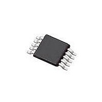
SI4010-C2-GT Silicon Laboratories Inc, SI4010-C2-GT Datasheet - Page 37

SI4010-C2-GT
Manufacturer Part Number
SI4010-C2-GT
Description
IC TX 27-960MHZ FSK 3.6V 10MSOP
Manufacturer
Silicon Laboratories Inc
Series
EZRadio®r
Type
Crystalless SoC RF Transmitterr
Datasheet
1.SI4010-C2-GT.pdf
(156 pages)
Specifications of SI4010-C2-GT
Package / Case
10-MSOP
Mfg Application Notes
SI4010 Calculator Spreadsheet AppNote
Frequency
27MHz ~ 960MHz
Applications
Garage Openers, RKE, Security Alarms
Modulation Or Protocol
FSK, OOK
Data Rate - Maximum
100 kBaud
Power - Output
10dBm
Current - Transmitting
19.8mA
Data Interface
PCB, Surface Mount
Antenna Connector
PCB, Surface Mount
Memory Size
4kB RAM
Features
8051 MCU Core, Crystal-less Operation
Voltage - Supply
1.8 V ~ 3.6 V
Operating Temperature
-40°C ~ 85°C
Operating Frequency
27 MHz to 960 MHz
Maximum Operating Temperature
+ 85 C
Mounting Style
SMD/SMT
Operating Supply Voltage
1.8 V to 3.6 V
Supply Current
14.2 mA
Lead Free Status / RoHS Status
Lead free / RoHS Compliant
Lead Free Status / RoHS Status
Lead free / RoHS Compliant, Lead free / RoHS Compliant
Other names
336-1997-5
Available stocks
Company
Part Number
Manufacturer
Quantity
Price
Part Number:
SI4010-C2-GT
Manufacturer:
SILICON LABS/èٹ¯ç§‘
Quantity:
20 000
Company:
Part Number:
SI4010-C2-GTR
Manufacturer:
ST
Quantity:
1 000
Part Number:
SI4010-C2-GTR
Manufacturer:
SILICON LABS/èٹ¯ç§‘
Quantity:
20 000
Si4010-C2
(PVT) to keep its quality factor (Q) nearly constant at 50 (at 434 MHz). The starting value of the 9-bit
capacitor word (XREG PA_CAP) is chosen with the help of the calculator spreadsheet. In general, a high
operating frequency requires a smaller capacitance and hence a low value capacitive word. The output
resistance of the PA is a strong function of the capacitive word because the variable capacitor is imple-
mented with a capacitor and a MOS switch. When more capacitance is turned on (higher capacitive word),
more switches turn on and with a constant Q design, the output resistance of the PA decreases and has
more loss. Thus another consideration for the nominal capacitive word besides the operating frequency is
how the resistive loading of the varactor affects the optimum load resistance and the required antenna
resistance. The calculator illustrates how the nominal value of the capacitive word affects the desired
antenna resistance.
In addition to the algorithm used to tune the antenna for resonance, a software control loop using the
Power Amplifier Module API can keep the transmit radiated power constant due to changes in temperature
and/or capacitance of the antenna. For example, if changes in the temperature of the transmitter and/or
the capacitance of the antenna cause the impedance of the load (the parallel combination of the PA and
antenna resistances) to decrease, this will cause a decrease in the output voltage of the PA and hence the
radiated power. Both the operating temperature and the capacitor tuning word are monitored by the chip
and may be used to increase the nominal drive current to bring the product of the output voltage and driver
capacitance back to what it was prior to the environmental change. In order for this loop to operate cor-
rectly, the parameters Alpha and Beta need to be determined from measured antenna characteristics.
Alpha represents the required change in bLevel (the nominal power level programmed through the API
interface) given changes in temperature. Beta represents the required change in bLevel given changes in
programmed driver capacitance. Remember that each LSB change in bLevel corresponds to a 0.25 dBm
change in power. For example, if experimental measurement shows that the radiated power changes by
1 dBm over a 50 °C change in temperature, alpha would be set to 4/50=0.08. In this alpha equation, the 4
is derived from 1 dBm/0.25 dBm per step in bLevel. Thus, the units of alpha are (LSB steps in
bLevel)/(change in temp). Beta can be determined using the Si4010 calculator spreadsheet. These two
parameters should be entered as parameters to the API to provide accurate adjustments to the radiated
power. In addition to these parameters, the differential peak voltage and current drive of the PA should not
be maximized prior to using this loop so adjustments in the current drive, which affects the differential peak
voltage, can be made by the feedback loop. If either the current or voltage is maximized prior to using the
loop, the loop would not be able to further adjust the current or voltage and hence fail to operate properly.
See “AN547: Si4010 Calculator Spreadsheet Usage” for more details.
Rev. 1.0
37


