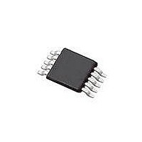
SI4010-C2-GT Silicon Laboratories Inc, SI4010-C2-GT Datasheet - Page 50

SI4010-C2-GT
Manufacturer Part Number
SI4010-C2-GT
Description
IC TX 27-960MHZ FSK 3.6V 10MSOP
Manufacturer
Silicon Laboratories Inc
Series
EZRadio®r
Type
Crystalless SoC RF Transmitterr
Datasheet
1.SI4010-C2-GT.pdf
(156 pages)
Specifications of SI4010-C2-GT
Package / Case
10-MSOP
Mfg Application Notes
SI4010 Calculator Spreadsheet AppNote
Frequency
27MHz ~ 960MHz
Applications
Garage Openers, RKE, Security Alarms
Modulation Or Protocol
FSK, OOK
Data Rate - Maximum
100 kBaud
Power - Output
10dBm
Current - Transmitting
19.8mA
Data Interface
PCB, Surface Mount
Antenna Connector
PCB, Surface Mount
Memory Size
4kB RAM
Features
8051 MCU Core, Crystal-less Operation
Voltage - Supply
1.8 V ~ 3.6 V
Operating Temperature
-40°C ~ 85°C
Operating Frequency
27 MHz to 960 MHz
Maximum Operating Temperature
+ 85 C
Mounting Style
SMD/SMT
Operating Supply Voltage
1.8 V to 3.6 V
Supply Current
14.2 mA
Lead Free Status / RoHS Status
Lead free / RoHS Compliant
Lead Free Status / RoHS Status
Lead free / RoHS Compliant, Lead free / RoHS Compliant
Other names
336-1997-5
Available stocks
Company
Part Number
Manufacturer
Quantity
Price
Part Number:
SI4010-C2-GT
Manufacturer:
SILICON LABS/èٹ¯ç§‘
Quantity:
20 000
Company:
Part Number:
SI4010-C2-GTR
Manufacturer:
ST
Quantity:
1 000
Part Number:
SI4010-C2-GTR
Manufacturer:
SILICON LABS/èٹ¯ç§‘
Quantity:
20 000
Si4010-C2
17. Frequency Counter
The frequency counter allows the measurement of the ratio of two selected clock sources: a low frequency
clock which defines a counting interval, and a high frequency clock which is counted.
The frequency counter consists of an interval counter, driven by one of the six clock sources. Programming
of the interval counter determines how long the main counter will count one of the two high speed clocks,
LC oscillator or DIVIDER output.
The block diagram of the frequency counter is in Figure 17.1. When the FC_MODE=0, the frequency coun-
ter is disabled. The only way to disable the frequency counter is to set the FC_MODE=0. The frequency
counter stops counting immediately, so it can be restarted by setting FC_MODE to some functional mode
immediately.
If the frequency counter is enabled by setting FC_MODE to other than the 0 value, it enters the idle state.
To start the counter, the interval counter has to be triggered by writing 1 to the FC_BUSY bit. By writing
FC_BUSY=1, the FC_DONE bit gets cleared as well. The user can also clear the FC_DONE bit in software
after reading the main FC_COUNT value.
Once the interval counter is triggered, and after several clk_sys cycles synchronization delay it waits for
the first rising edge of the clk_int clock, which is the output of the interval counter clock selector mux. It
then enables the main frequency counter FC_COUNT clock. After the interval counter counts the interval
specified by FC_INTERVAL SFR register, another rising edge of the clk_int stops the clocks to the main
FC_COUNT counter. The interval counter edge to edge counting and main FC_COUNT clock enable is
measured very accurately in between the clk_int rising edges.
50
GPIO[3]
GPIO[0]
Controller
Oscillator
Port
Xtal
Figure 17.1. Frequency Counter Block Diagram
LC_OSC/2
DIVIDER
RESERVED
clk_osc (24MHz)
clk_ref
clk_xo
SLEEP TIMER
RESERVED
0
1
clk_sys
Freq counter
FC_CTRL
disabled
0
1
2
3
4
5
5
7
Rev. 1.0
3
clk_int
New count trigger
FC_INTERVAL
Counter
Interval
Long word 4 byte result count
read from XREG
(LWORD lFcCount)
FC_COUNT
FC_DONE
FC_BUSY
FC_DIV_SEL
FC_MODE
Interrupt


