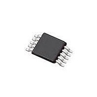
SI4010-C2-GT Silicon Laboratories Inc, SI4010-C2-GT Datasheet - Page 149

SI4010-C2-GT
Manufacturer Part Number
SI4010-C2-GT
Description
IC TX 27-960MHZ FSK 3.6V 10MSOP
Manufacturer
Silicon Laboratories Inc
Series
EZRadio®r
Type
Crystalless SoC RF Transmitterr
Datasheet
1.SI4010-C2-GT.pdf
(156 pages)
Specifications of SI4010-C2-GT
Package / Case
10-MSOP
Mfg Application Notes
SI4010 Calculator Spreadsheet AppNote
Frequency
27MHz ~ 960MHz
Applications
Garage Openers, RKE, Security Alarms
Modulation Or Protocol
FSK, OOK
Data Rate - Maximum
100 kBaud
Power - Output
10dBm
Current - Transmitting
19.8mA
Data Interface
PCB, Surface Mount
Antenna Connector
PCB, Surface Mount
Memory Size
4kB RAM
Features
8051 MCU Core, Crystal-less Operation
Voltage - Supply
1.8 V ~ 3.6 V
Operating Temperature
-40°C ~ 85°C
Operating Frequency
27 MHz to 960 MHz
Maximum Operating Temperature
+ 85 C
Mounting Style
SMD/SMT
Operating Supply Voltage
1.8 V to 3.6 V
Supply Current
14.2 mA
Lead Free Status / RoHS Status
Lead free / RoHS Compliant
Lead Free Status / RoHS Status
Lead free / RoHS Compliant, Lead free / RoHS Compliant
Other names
336-1997-5
Available stocks
Company
Part Number
Manufacturer
Quantity
Price
Part Number:
SI4010-C2-GT
Manufacturer:
SILICON LABS/èٹ¯ç§‘
Quantity:
20 000
Company:
Part Number:
SI4010-C2-GTR
Manufacturer:
ST
Quantity:
1 000
Part Number:
SI4010-C2-GTR
Manufacturer:
SILICON LABS/èٹ¯ç§‘
Quantity:
20 000
Si4010-C2
On this device the GPIO[5] is shared with the LED current driver, which can drive up to 1mA of current to
the ground. Normally the LED will be connected in between the GPIO[5] and VDD. For C2 to work the LED
driver is disabled during debugging sessions, so even if the user code tries to turn the LED on, that opera-
tion will not interfere with C2 debug transactions and the actual LED current driver will not be turned on.
Whenever the user disconnects the IDE from the device by hitting the Disconnect button on the IDE, the
IDE clears all the breakpoints, clears the LED driver disable (enables the LED), and runs the currently
loaded user application residing in the CODE/XDATA RAM from the current position where the code was
halted. If IDE is disconnected from the device the user application behaves exactly as programmed, with
the LED driver driving the LED per user application. The user then can connect to the device through IDE
by hitting the Connect button. The connection is only possible when the LED driver is not active. Upon
connection the IDE will disable the LED driver for the duration of the debug session (until the device is
Disconnect-ed).
The GPIO[4] can be used as a bidirectional input/output by a user application, but a resistive network has
to be used to isolate the GPIO[4] from the C2 transactions, as shown in Figure 35.1.
Instead of the USB debug adapter the user can also use Silicon Labs ToolStick development tool. The
ToolStick has a PCB edge 14 pin connector. Connection in between the device and the ToolStick for soft-
ware development and debugging is in Figure 35.2.
Rev. 1.0
149


