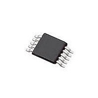
SI4010-C2-GT Silicon Laboratories Inc, SI4010-C2-GT Datasheet - Page 148

SI4010-C2-GT
Manufacturer Part Number
SI4010-C2-GT
Description
IC TX 27-960MHZ FSK 3.6V 10MSOP
Manufacturer
Silicon Laboratories Inc
Series
EZRadio®r
Type
Crystalless SoC RF Transmitterr
Datasheet
1.SI4010-C2-GT.pdf
(156 pages)
Specifications of SI4010-C2-GT
Package / Case
10-MSOP
Mfg Application Notes
SI4010 Calculator Spreadsheet AppNote
Frequency
27MHz ~ 960MHz
Applications
Garage Openers, RKE, Security Alarms
Modulation Or Protocol
FSK, OOK
Data Rate - Maximum
100 kBaud
Power - Output
10dBm
Current - Transmitting
19.8mA
Data Interface
PCB, Surface Mount
Antenna Connector
PCB, Surface Mount
Memory Size
4kB RAM
Features
8051 MCU Core, Crystal-less Operation
Voltage - Supply
1.8 V ~ 3.6 V
Operating Temperature
-40°C ~ 85°C
Operating Frequency
27 MHz to 960 MHz
Maximum Operating Temperature
+ 85 C
Mounting Style
SMD/SMT
Operating Supply Voltage
1.8 V to 3.6 V
Supply Current
14.2 mA
Lead Free Status / RoHS Status
Lead free / RoHS Compliant
Lead Free Status / RoHS Status
Lead free / RoHS Compliant, Lead free / RoHS Compliant
Other names
336-1997-5
Available stocks
Company
Part Number
Manufacturer
Quantity
Price
Part Number:
SI4010-C2-GT
Manufacturer:
SILICON LABS/èٹ¯ç§‘
Quantity:
20 000
Company:
Part Number:
SI4010-C2-GTR
Manufacturer:
ST
Quantity:
1 000
Part Number:
SI4010-C2-GTR
Manufacturer:
SILICON LABS/èٹ¯ç§‘
Quantity:
20 000
Si4010-C2
35. C2 Interface
The devices include an on-chip Silicon Laboratories 2-Wire (C2) debug interface in-system debugging with
the production part installed in the end application. The C2 interface uses a clock signal (C2CLK) and a bi-
directional C2 data signal (C2DAT) to transfer information between the device and a host system. The C2
interface is intended to be used by the Silicon Labs or third party development tools. It is not intended to be
used for any other purpose. It can be completely disabled per user programming for fully programmed
chips.
35.1. C2 Pin Sharing
The C2 protocol allows the C2 pins to be shared with user functions so that in-system debugging. This is
possible because C2 communication is typically performed when the device is in the halt state, where all
on-chip peripherals and user software are stalled. In this halted state, the C2 interface can safely borrow
the C2CLK (GPIO[5]) and C2DAT (GPIO[4]) pins. In most applications, external resistors are required to
isolate C2 interface traffic from the user application. A typical isolation configuration is shown in
Figure 35.1 along with the connection to the standard Silicon Labs 10-pin debugging interface header.
148
Figure 35.1. 10-pin C2 USB Debugging Adapter Connection to Device
R4
1k
For debugging chain to
work, LED must be
isolated by R6
TMS
C2CLK
If pushbutton on keyfob
development board, then it
has to be isolated by R5
USB debug adapter
10 pin header connector
SW_GPIO4
1
3
5
7
9
R6
VDD
2
4
6
8
10
470
LED
1k5
R5
R2
1k
Rev. 1.0
For application bidirectional use,
isolated from the C2
1k
GPIO[4]
R1
C2DAT
C2CLK
VBUS (~ +4.6V) Can be used to
GPIO4
GPIO5
VDD
1mA max
50k
generate local VDD
VDD
50k
Device
VDD


