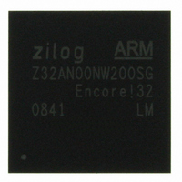
Z32AN00NW200SG Zilog, Z32AN00NW200SG Datasheet - Page 118

Z32AN00NW200SG
Manufacturer Part Number
Z32AN00NW200SG
Description
IC ARM922T MCU 200MHZ 256-BGA
Manufacturer
Zilog
Series
Encore!® 32r
Datasheet
1.Z32AN00NW200SG.pdf
(196 pages)
Specifications of Z32AN00NW200SG
Core Processor
ARM9
Core Size
16/32-Bit
Speed
200MHz
Connectivity
EBI/EMI, IrDA, SmartCard, SPI, UART/USART, USB OTG
Peripherals
DMA, LCD, Magnetic Card Reader, POR, PWM, WDT
Number Of I /o
76
Program Memory Type
ROMless
Ram Size
64K x 8
Voltage - Supply (vcc/vdd)
1.71 V ~ 3.6 V
Data Converters
A/D 4x10b
Oscillator Type
Internal
Operating Temperature
-40°C ~ 85°C
Package / Case
256-LBGA
For Use With
269-4713 - KIT DEV ENCORE 32 SERIES
Lead Free Status / RoHS Status
Lead free / RoHS Compliant
Eeprom Size
-
Program Memory Size
-
Other names
269-4717
Available stocks
Company
Part Number
Manufacturer
Quantity
Price
- Current page: 118 of 196
- Download datasheet (4Mb)
Z32AN Series Data Sheet
Chapter 14: Analog-to-Digital Converter (ADC)
14.1 Voltage Reference
14.2 Clock / Sample Rate
14.3 Modes of Operation
14.3.1 Continuous Rotating
14.3.2 Single Shot
14.4 DMA Operation
DS0200-003
The ADC is an APB device with the following features:
The ADC requires an external V
V
performance.
The ADC clock is derived from hclk. ADC_CFG is used to configure the divider from 2 up to 256. This value
must be selected to produce an ADC clock slower than 540 kHz. The conversion time is 12 ADC clocks
which provides a maximum sample rate of 45 kHz.
In this mode, the ADC samples every 12 ADC clocks and is capable of rotating between the 6 input
channels. To use this mode, decide the number of samples to be in the rotation. This can range from 1–8
and is programmed in ADC_CMD. The channels sampled are programmed in ADC_CFG. Start the
sequence by setting ADC_CMD.COMP_SMPL to ‘1’. Sampling is stopped by clearing this bit.
This mode performs one sample of a single channel. To use this mode, select the channel in ADC_CFG
and then set ADC_CMD.SNGL_SMPL to ‘1’. Once sampling is complete, it is placed in the FIFO.
DMA requests can be generated based on the number of entries in the FIFO. ADC_INT.FIFO_LEVEL and
ADC_INT.REQ_EN are used to control DMA requests.
REF
can be tied to the analog V
10-bit resolution, 45 kHz, successive-approximation ADC
Multiplexing to support 4 channel inputs
4 sample FIFO
Support for DMA
SINGLE SHOT or CONTINUOUS sample modes
Programmable ADC clock
12 cycle conversion time (ADC clock cycles)
Power down to <1 µA
Differential Nonlinearity
Integral Nonlinearity (INL) ± 2 LSB
Example 1 (channel 3):
Channel 3 is sampled continuously at the rate of ADC Clock / 12.
Example 2 (channel 1,2,1,3):
ACH_SEL=001, BCH_SEL=010, CCH_SEL=001, and DCH_SEL=011. This samples 1-2-1-3 -
- 1-2-1-3 -- etc. (A,B,C,D -- A,B,C,D -- etc.) continuously at the rate of ADC clock / 12.
REF
(
DNL) ± 1 LSB
. The accuracy of conversions depends on the quality of V
DD
ADC_CMD.ROT_LIMIT=001, and ADC_CFG.ACH_SEL = 001.
for the ADC but be sure to filter the noise to achieve optimum
ADC_CMD.ROT_LIMIT=100, and ADC_CFG fields
REF
Page 105
supplied.
Related parts for Z32AN00NW200SG
Image
Part Number
Description
Manufacturer
Datasheet
Request
R

Part Number:
Description:
Communication Controllers, ZILOG INTELLIGENT PERIPHERAL CONTROLLER (ZIP)
Manufacturer:
Zilog, Inc.
Datasheet:

Part Number:
Description:
KIT DEV FOR Z8 ENCORE 16K TO 64K
Manufacturer:
Zilog
Datasheet:

Part Number:
Description:
KIT DEV Z8 ENCORE XP 28-PIN
Manufacturer:
Zilog
Datasheet:

Part Number:
Description:
DEV KIT FOR Z8 ENCORE 8K/4K
Manufacturer:
Zilog
Datasheet:

Part Number:
Description:
KIT DEV Z8 ENCORE XP 28-PIN
Manufacturer:
Zilog
Datasheet:

Part Number:
Description:
DEV KIT FOR Z8 ENCORE 4K TO 8K
Manufacturer:
Zilog
Datasheet:

Part Number:
Description:
CMOS Z8 microcontroller. ROM 16 Kbytes, RAM 256 bytes, speed 16 MHz, 32 lines I/O, 3.0V to 5.5V
Manufacturer:
Zilog, Inc.
Datasheet:

Part Number:
Description:
Low-cost microcontroller. 512 bytes ROM, 61 bytes RAM, 8 MHz
Manufacturer:
Zilog, Inc.
Datasheet:

Part Number:
Description:
Z8 4K OTP Microcontroller
Manufacturer:
Zilog, Inc.
Datasheet:

Part Number:
Description:
CMOS SUPER8 ROMLESS MCU
Manufacturer:
Zilog, Inc.
Datasheet:

Part Number:
Description:
SL1866 CMOSZ8 OTP Microcontroller
Manufacturer:
Zilog, Inc.
Datasheet:

Part Number:
Description:
SL1866 CMOSZ8 OTP Microcontroller
Manufacturer:
Zilog, Inc.
Datasheet:

Part Number:
Description:
OTP (KB) = 1, RAM = 125, Speed = 12, I/O = 14, 8-bit Timers = 2, Comm Interfaces Other Features = Por, LV Protect, Voltage = 4.5-5.5V
Manufacturer:
Zilog, Inc.
Datasheet:

Part Number:
Description:
Manufacturer:
Zilog, Inc.
Datasheet:


