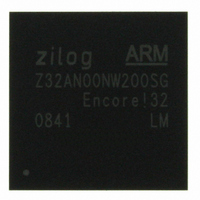
Z32AN00NW200SG Zilog, Z32AN00NW200SG Datasheet - Page 75

Z32AN00NW200SG
Manufacturer Part Number
Z32AN00NW200SG
Description
IC ARM922T MCU 200MHZ 256-BGA
Manufacturer
Zilog
Series
Encore!® 32r
Datasheet
1.Z32AN00NW200SG.pdf
(196 pages)
Specifications of Z32AN00NW200SG
Core Processor
ARM9
Core Size
16/32-Bit
Speed
200MHz
Connectivity
EBI/EMI, IrDA, SmartCard, SPI, UART/USART, USB OTG
Peripherals
DMA, LCD, Magnetic Card Reader, POR, PWM, WDT
Number Of I /o
76
Program Memory Type
ROMless
Ram Size
64K x 8
Voltage - Supply (vcc/vdd)
1.71 V ~ 3.6 V
Data Converters
A/D 4x10b
Oscillator Type
Internal
Operating Temperature
-40°C ~ 85°C
Package / Case
256-LBGA
For Use With
269-4713 - KIT DEV ENCORE 32 SERIES
Lead Free Status / RoHS Status
Lead free / RoHS Compliant
Eeprom Size
-
Program Memory Size
-
Other names
269-4717
Available stocks
Company
Part Number
Manufacturer
Quantity
Price
- Current page: 75 of 196
- Download datasheet (4Mb)
Z32AN Series Data Sheet
9.2.3
9.2.4
9.2.5
9.2.6
DS0200-003
Each track has an internal 12-bit timer which is used to calculate the delta-time between peaks that
increments with every sample of the ADC. In addition to calculating the delta-time, this timer is used to
detect when peaks are no longer being received by the MCR (indicating the end of a card swipe).
All three timers will only count up to the maximum value specified in the MCR_TMR. Should any timer count
up to that value, a time-out condition will occur for that track. Under this condition, the last valid delta-time
entry will be stored in the FIFO and the timer will be disabled (preventing further time-out interrupts). Once
another threshold crossing occurs, the timer will be automatically re-enabled and the search for time-out
conditions begins again.
As described above, each track has an internal 12-bit timer. An interrupt can be generated on the time-out of
each track, or a single time-out can be generated on the time-out of the “last” track. This simplifies MCR
interrupt handling. A time-out is considered to be the “last” if the other two timers are either: 1) not enabled;
2) already timed-out; or 3) have not encountered an initial peak (never started).
The card time-out is enabled by setting MCR_CTRL.CART_TO_IEN.
There are two modes of operation for threshold values, selected by MCR_CTRL.THRESH. The first mode is
static threshold mode. In this mode, the positive minimum threshold and the negative minimum threshold
programmed by the user are always the thresholds used by the peak detector.
The second mode is dynamic threshold mode. In this mode, the previous peak is scaled by 1/4, 1/8, or 1/16
to generate a temporary internal threshold for the next peak (the values in MCRn_THRS do not change). If
the scaled value is ever computed to be less than the value of MCRn_THRS, then that minimum value is
used instead of the scaled version (i.e. the thresholds can never be less than the programmed values). In
the event of a time-out, both thresholds revert to the programmed value.
Below are the registers and fields which are used to control and handle DMA interrupts.
Status bits are set whenever the corresponding event occurs whether or not the corresponding enable bit is
set. These bits remain set (latched) until cleared by a write to MCR_INT. Whenever a status bit and
corresponding enable bit are active, an interrupt is generated.
Peak Detection Timer and Time-out
Card Time-out and Track Timers
Dynamic Minimum Thresholds
MCR Interrupts
MCR_CTRL.CARD_TO_IEN → MCR_INT.CARD_TO
MCR_CTRL.AUX_ADC_IEN → MCR_INT.AUX_ADC
MCR_CTRL.UFLO_IEN → MCR_INT.UFLO
MCR_CTRL.OFLO_IEN → MCR_INT.OFLO
MCR_CTRL.LVL_IEN → MCR_INT.LVL
MCR_CTRL.TOn_IEN → MCR_INT.TOn
MCR_INT.STA
Page 62
Related parts for Z32AN00NW200SG
Image
Part Number
Description
Manufacturer
Datasheet
Request
R

Part Number:
Description:
Communication Controllers, ZILOG INTELLIGENT PERIPHERAL CONTROLLER (ZIP)
Manufacturer:
Zilog, Inc.
Datasheet:

Part Number:
Description:
KIT DEV FOR Z8 ENCORE 16K TO 64K
Manufacturer:
Zilog
Datasheet:

Part Number:
Description:
KIT DEV Z8 ENCORE XP 28-PIN
Manufacturer:
Zilog
Datasheet:

Part Number:
Description:
DEV KIT FOR Z8 ENCORE 8K/4K
Manufacturer:
Zilog
Datasheet:

Part Number:
Description:
KIT DEV Z8 ENCORE XP 28-PIN
Manufacturer:
Zilog
Datasheet:

Part Number:
Description:
DEV KIT FOR Z8 ENCORE 4K TO 8K
Manufacturer:
Zilog
Datasheet:

Part Number:
Description:
CMOS Z8 microcontroller. ROM 16 Kbytes, RAM 256 bytes, speed 16 MHz, 32 lines I/O, 3.0V to 5.5V
Manufacturer:
Zilog, Inc.
Datasheet:

Part Number:
Description:
Low-cost microcontroller. 512 bytes ROM, 61 bytes RAM, 8 MHz
Manufacturer:
Zilog, Inc.
Datasheet:

Part Number:
Description:
Z8 4K OTP Microcontroller
Manufacturer:
Zilog, Inc.
Datasheet:

Part Number:
Description:
CMOS SUPER8 ROMLESS MCU
Manufacturer:
Zilog, Inc.
Datasheet:

Part Number:
Description:
SL1866 CMOSZ8 OTP Microcontroller
Manufacturer:
Zilog, Inc.
Datasheet:

Part Number:
Description:
SL1866 CMOSZ8 OTP Microcontroller
Manufacturer:
Zilog, Inc.
Datasheet:

Part Number:
Description:
OTP (KB) = 1, RAM = 125, Speed = 12, I/O = 14, 8-bit Timers = 2, Comm Interfaces Other Features = Por, LV Protect, Voltage = 4.5-5.5V
Manufacturer:
Zilog, Inc.
Datasheet:

Part Number:
Description:
Manufacturer:
Zilog, Inc.
Datasheet:


