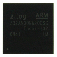
Z32AN00NW200SG Zilog, Z32AN00NW200SG Datasheet - Page 144

Z32AN00NW200SG
Manufacturer Part Number
Z32AN00NW200SG
Description
IC ARM922T MCU 200MHZ 256-BGA
Manufacturer
Zilog
Series
Encore!® 32r
Datasheet
1.Z32AN00NW200SG.pdf
(196 pages)
Specifications of Z32AN00NW200SG
Core Processor
ARM9
Core Size
16/32-Bit
Speed
200MHz
Connectivity
EBI/EMI, IrDA, SmartCard, SPI, UART/USART, USB OTG
Peripherals
DMA, LCD, Magnetic Card Reader, POR, PWM, WDT
Number Of I /o
76
Program Memory Type
ROMless
Ram Size
64K x 8
Voltage - Supply (vcc/vdd)
1.71 V ~ 3.6 V
Data Converters
A/D 4x10b
Oscillator Type
Internal
Operating Temperature
-40°C ~ 85°C
Package / Case
256-LBGA
For Use With
269-4713 - KIT DEV ENCORE 32 SERIES
Lead Free Status / RoHS Status
Lead free / RoHS Compliant
Eeprom Size
-
Program Memory Size
-
Other names
269-4717
Available stocks
Company
Part Number
Manufacturer
Quantity
Price
- Current page: 144 of 196
- Download datasheet (4Mb)
Z32AN Series Data Sheet
17.2.4 DMA mode Transfers
17.3 Baud Rate Generator (BRG)
17.4 Infrared Encoder/Decoder (UART2 only)
DS0200-003
DMA is enabled by setting UARTx_FCR.DMA to ‘1’, disabling the corresponding interrupt(s) and selecting
the UART transmit and/or receive devices. The assertion of DMA requests is controlled by the
UARTx_FCR.TRIG.
A transmit DMA request is asserted when there are TRIG or fewer bytes in the transmit FIFO. The transmit
DMA burst size must be set to less than or equal to 16-TRIG bytes to prevent overrunning the transmit
FIFO. A receive DMA request is asserted when there are TRIG or more bytes in the receive FIFO. The
receive DMA burst size can be set for up to TRIG bytes.
When receive DMA is enabled, UARTx_IER.LSIE must be set to catch errors that prevent DMA completion.
The BRG consists of a 16-bit counter, two registers, and associated decoding logic. The initial value of the
BRG is defined by UARTx_BRG_H and UARTx_BRG_L. At the rising edge of each hclk, the BRG
decrements until 0001h. On the next hclk rising edge, it reloads the initial value from UARTx_BRG_H and
UARTx_BRG_L and outputs a pulse to indicate the end-of-count. UART data rate can be calculated as
follows:
On RESET, the BRG divisor value resets to the smallest allowable value of 0002h. Therefore, the minimum
BRG clock divisor ratio is 2. A write to either UARTx_BRG_H or UARTx_BRG_L causes both bytes to load
into the BRG counter, restarting the count. The divisor registers can only be accessed if UARTx_LCR.DLAB
is set to ‘1’. Following is the normal sequence of operations to configure the Baud Rate Generator:
UART2 integrates an infrared encoder/decoder (endec) to allow easy communication between the Z32AN
Series SoC and an IrDA Physical Layer Specification Version 1.3 compliant device, as shown in Figure 17-1.
When enabled, transmit data from UART2 is encoded as digital signals in accordance with the IrDA
standard and output to the infrared transceiver. Likewise, data received from the infrared transceiver is
decoded by the endec and passed to UART2. Communication is half-duplex meaning that simultaneous
data transmission and reception is not allowed. The baud rate is set by the UART BRG and supports baud
rates from 9600 bps to 115.2 kbps. Higher baud rates are possible, but do not meet IrDA specifications.
1.
4.
5.
Set UARTx_LCR[7] to 1 to enable access of the BRG divisor registers
Program the UARTx_BRG_L and UARTx_BRG_H registers
Clear UARTx_LCR[7] to 0 to disable access of the BRG divisor registers
Figure 17-1: Infrared System Block Diagram
Page 131
Related parts for Z32AN00NW200SG
Image
Part Number
Description
Manufacturer
Datasheet
Request
R

Part Number:
Description:
Communication Controllers, ZILOG INTELLIGENT PERIPHERAL CONTROLLER (ZIP)
Manufacturer:
Zilog, Inc.
Datasheet:

Part Number:
Description:
KIT DEV FOR Z8 ENCORE 16K TO 64K
Manufacturer:
Zilog
Datasheet:

Part Number:
Description:
KIT DEV Z8 ENCORE XP 28-PIN
Manufacturer:
Zilog
Datasheet:

Part Number:
Description:
DEV KIT FOR Z8 ENCORE 8K/4K
Manufacturer:
Zilog
Datasheet:

Part Number:
Description:
KIT DEV Z8 ENCORE XP 28-PIN
Manufacturer:
Zilog
Datasheet:

Part Number:
Description:
DEV KIT FOR Z8 ENCORE 4K TO 8K
Manufacturer:
Zilog
Datasheet:

Part Number:
Description:
CMOS Z8 microcontroller. ROM 16 Kbytes, RAM 256 bytes, speed 16 MHz, 32 lines I/O, 3.0V to 5.5V
Manufacturer:
Zilog, Inc.
Datasheet:

Part Number:
Description:
Low-cost microcontroller. 512 bytes ROM, 61 bytes RAM, 8 MHz
Manufacturer:
Zilog, Inc.
Datasheet:

Part Number:
Description:
Z8 4K OTP Microcontroller
Manufacturer:
Zilog, Inc.
Datasheet:

Part Number:
Description:
CMOS SUPER8 ROMLESS MCU
Manufacturer:
Zilog, Inc.
Datasheet:

Part Number:
Description:
SL1866 CMOSZ8 OTP Microcontroller
Manufacturer:
Zilog, Inc.
Datasheet:

Part Number:
Description:
SL1866 CMOSZ8 OTP Microcontroller
Manufacturer:
Zilog, Inc.
Datasheet:

Part Number:
Description:
OTP (KB) = 1, RAM = 125, Speed = 12, I/O = 14, 8-bit Timers = 2, Comm Interfaces Other Features = Por, LV Protect, Voltage = 4.5-5.5V
Manufacturer:
Zilog, Inc.
Datasheet:

Part Number:
Description:
Manufacturer:
Zilog, Inc.
Datasheet:


