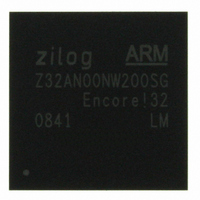
Z32AN00NW200SG Zilog, Z32AN00NW200SG Datasheet - Page 7

Z32AN00NW200SG
Manufacturer Part Number
Z32AN00NW200SG
Description
IC ARM922T MCU 200MHZ 256-BGA
Manufacturer
Zilog
Series
Encore!® 32r
Datasheet
1.Z32AN00NW200SG.pdf
(196 pages)
Specifications of Z32AN00NW200SG
Core Processor
ARM9
Core Size
16/32-Bit
Speed
200MHz
Connectivity
EBI/EMI, IrDA, SmartCard, SPI, UART/USART, USB OTG
Peripherals
DMA, LCD, Magnetic Card Reader, POR, PWM, WDT
Number Of I /o
76
Program Memory Type
ROMless
Ram Size
64K x 8
Voltage - Supply (vcc/vdd)
1.71 V ~ 3.6 V
Data Converters
A/D 4x10b
Oscillator Type
Internal
Operating Temperature
-40°C ~ 85°C
Package / Case
256-LBGA
For Use With
269-4713 - KIT DEV ENCORE 32 SERIES
Lead Free Status / RoHS Status
Lead free / RoHS Compliant
Eeprom Size
-
Program Memory Size
-
Other names
269-4717
Available stocks
Company
Part Number
Manufacturer
Quantity
Price
Z32AN Series Data Sheet
DS0200-003
Chapter 8: DMA Controller........................................................................................... 49
Chapter 9: Magnetic Card Reader (MCR) ................................................................. 60
Chapter 10: Smart Card Controller ............................................................................. 69
8.1 Channel Arbitration and Bursts......................................................................................................... 49
8.2 DMA Source and Destination Addressing ...................................................................................... 50
8.3 Data Movement from the DMA FIFO to the Destination ............................................................. 51
8.4 Memory Buffer Alignment ................................................................................................................. 51
8.5 Count-to-Zero Condition ................................................................................................................... 52
8.6 Chaining Buffers .................................................................................................................................. 52
8.7 DMA Interrupts..................................................................................................................................... 52
8.8 Channel Time-outs.............................................................................................................................. 52
8.9 Register Accesses Restrictions .......................................................................................................... 53
8.10 Memory-to-Memory DMA ................................................................................................................. 53
8.11 External DMA ....................................................................................................................................... 53
8.12 Registers (Base → FFFF4000h)............................................................................................................ 54
9.1 Magnetic Card Reading Overview................................................................................................. 60
9.2 Direct Mode Operation of MCR....................................................................................................... 61
9.3 Registers (Base → FFFF3000h)............................................................................................................ 64
10.1 SPI Interface ......................................................................................................................................... 69
10.2 Blocks .................................................................................................................................................... 71
10.3 Registers................................................................................................................................................ 74
8.12.1 Global Registers................................................................................................................54
8.12.2 Per-Channel Registers ......................................................................................................55
9.2.1
9.2.2
9.2.3
9.2.4
9.2.5
9.2.6
9.2.7
9.2.8
9.2.9
9.3.1
9.3.2
9.3.3
9.3.4
9.3.5
9.3.6
9.3.7
9.3.8
10.1.1 Smart Card Controller Interrupt Management .............................................................69
10.1.2 Reset and Power-up Management ...............................................................................70
10.1.3 Chip to Smart Card Interface Mapping ........................................................................70
10.1.4 DMA Interface ..................................................................................................................70
10.1.5 Synchronous Smart Card Handling ................................................................................70
10.1.6 Interrupt Generation ........................................................................................................70
10.2.1 UART ...................................................................................................................................71
10.2.2 Programmable Baud Rate Generator (BRG) ................................................................71
10.2.3 Controller...........................................................................................................................72
10.2.4 Timing Checker.................................................................................................................73
10.2.5 Interrupt Generation ........................................................................................................73
10.3.1 Global Registers (Base → FFFF0000h) .............................................................................74
10.3.2 Smart Card UART Mode Registers (Base: SC0 → FFFF0100h, SC1 → FFFF0200h).........79
10.3.3 Smart Card Controller Registers (Base: SC0 → FFFF0100h, SC1 → FFFF0200h)............86
Peak Detection Algorithm ...............................................................................................61
Stored Peak Information ..................................................................................................61
Peak Detection Timer and Time-out...............................................................................62
Card Time-out and Track Timers .....................................................................................62
Dynamic Minimum Thresholds.........................................................................................62
MCR Interrupts ..................................................................................................................62
Acquiring Raw ADC Samples..........................................................................................63
Programming Guide ........................................................................................................63
Card Time-out and Track Timers .....................................................................................64
Offset 000h: MCR_CTRL – MCR Control Register ...........................................................65
Offset 004h: MCR_INT – MCR Interrupt Register .............................................................66
Offset 008h: MCR_TMR – MCR Timing Register ..............................................................66
Offset 00Ch: MCR_FIFO – MCR FIFO Register.................................................................67
Offset 010h: MCR_ADC – MCR ADC Register ................................................................67
MCRn_DCO – MCR DC Offset Registers (MCR0: 014h, MCR1: 018h, MCR2: 01Ch)...68
MCRn_THRS – MCR Threshold Registers (MCR0: 020h, MCR1: 024h, MCR2: 028h) .....68
Offset 02Ch: MCR_AUX_ADC – MCR Auxiliary ADC Register .......................................68
Page v


