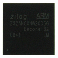
Z32AN00NW200SG Zilog, Z32AN00NW200SG Datasheet - Page 126

Z32AN00NW200SG
Manufacturer Part Number
Z32AN00NW200SG
Description
IC ARM922T MCU 200MHZ 256-BGA
Manufacturer
Zilog
Series
Encore!® 32r
Datasheet
1.Z32AN00NW200SG.pdf
(196 pages)
Specifications of Z32AN00NW200SG
Core Processor
ARM9
Core Size
16/32-Bit
Speed
200MHz
Connectivity
EBI/EMI, IrDA, SmartCard, SPI, UART/USART, USB OTG
Peripherals
DMA, LCD, Magnetic Card Reader, POR, PWM, WDT
Number Of I /o
76
Program Memory Type
ROMless
Ram Size
64K x 8
Voltage - Supply (vcc/vdd)
1.71 V ~ 3.6 V
Data Converters
A/D 4x10b
Oscillator Type
Internal
Operating Temperature
-40°C ~ 85°C
Package / Case
256-LBGA
For Use With
269-4713 - KIT DEV ENCORE 32 SERIES
Lead Free Status / RoHS Status
Lead free / RoHS Compliant
Eeprom Size
-
Program Memory Size
-
Other names
269-4717
Available stocks
Company
Part Number
Manufacturer
Quantity
Price
- Current page: 126 of 196
- Download datasheet (4Mb)
Z32AN Series Data Sheet
Chapter 16: Timers
16.1 Watchdog Timer (WDT)
16.1.1 Enabling
16.1.2 Time Delay Period Selection
DS0200-003
The WDT is an APB device that protects against conditions that may place the microcontroller into an
unsuitable operating state. When enabled, the WDT periodically sends interrupts and waits for interrupt
service. If software does not respond by servicing the interrupt within a pre-defined time and WDT reset is
enabled, the WDT sends a system reset request to the Power Management Unit (PMU). The WDT features
sixteen programmable time delay periods, 2
Timer is shown below.
Software sets WDT_CTL.WDT_EN to ‘1’ to enable the WDT. The WDT can be disabled by system reset or
clearing WDT_CTL.WDT_EN to ‘0’.
WDT_CTL.INT_EN and WDT_CTL.RST_EN.
There are two independent time delay periods can be specified in the WDT, an “interrupt period”, which
specifies the time delay before the WDT sends an interrupt to the CPU, and a “reset period”, which specifies
the time delay before the WDT sends a system reset request to the PMU if the interrupt is not serviced.
After the interrupt is generated, software services it with a sequence of writes to WDT_RR. If the interrupt is
not serviced within this timeframe and the WDT reset is enabled, the WDT sends a system reset request
(RESET) to the PMU. Figure 15-1 shows the timing diagrams for interrupt and reset.
There are sixteen choices of time delay periods for the WDT—2
delay for a specific clock source can be calculated by the following equation:
Up Counter
Interrupt
32-Bit
RESET
Table 16-1: Watchdog Timer Approximate time Delays
Clock Source
90 MHz hclk
90 MHz hclk
Figure 16-1: Interrupt and RESET Timing Diagram
90 MHz hclk
90 MHz hclk
0 1 2 3
INT_PERIOD
Interrupt and reset from the WDT is controlled through
16
. . .
through 2
Divider Value
RST_PERIOD
2
2
2
2
18
22
25
27
31
clock cycles. The architecture for the Watchdog
16
, 2
17
, 2
Time Delay
0 1 2
18
Completion of Service
47ms
Routine
, through 2
3ms
0.4s
1.5s
31
hclk cycles. The time
Page 113
Related parts for Z32AN00NW200SG
Image
Part Number
Description
Manufacturer
Datasheet
Request
R

Part Number:
Description:
Communication Controllers, ZILOG INTELLIGENT PERIPHERAL CONTROLLER (ZIP)
Manufacturer:
Zilog, Inc.
Datasheet:

Part Number:
Description:
KIT DEV FOR Z8 ENCORE 16K TO 64K
Manufacturer:
Zilog
Datasheet:

Part Number:
Description:
KIT DEV Z8 ENCORE XP 28-PIN
Manufacturer:
Zilog
Datasheet:

Part Number:
Description:
DEV KIT FOR Z8 ENCORE 8K/4K
Manufacturer:
Zilog
Datasheet:

Part Number:
Description:
KIT DEV Z8 ENCORE XP 28-PIN
Manufacturer:
Zilog
Datasheet:

Part Number:
Description:
DEV KIT FOR Z8 ENCORE 4K TO 8K
Manufacturer:
Zilog
Datasheet:

Part Number:
Description:
CMOS Z8 microcontroller. ROM 16 Kbytes, RAM 256 bytes, speed 16 MHz, 32 lines I/O, 3.0V to 5.5V
Manufacturer:
Zilog, Inc.
Datasheet:

Part Number:
Description:
Low-cost microcontroller. 512 bytes ROM, 61 bytes RAM, 8 MHz
Manufacturer:
Zilog, Inc.
Datasheet:

Part Number:
Description:
Z8 4K OTP Microcontroller
Manufacturer:
Zilog, Inc.
Datasheet:

Part Number:
Description:
CMOS SUPER8 ROMLESS MCU
Manufacturer:
Zilog, Inc.
Datasheet:

Part Number:
Description:
SL1866 CMOSZ8 OTP Microcontroller
Manufacturer:
Zilog, Inc.
Datasheet:

Part Number:
Description:
SL1866 CMOSZ8 OTP Microcontroller
Manufacturer:
Zilog, Inc.
Datasheet:

Part Number:
Description:
OTP (KB) = 1, RAM = 125, Speed = 12, I/O = 14, 8-bit Timers = 2, Comm Interfaces Other Features = Por, LV Protect, Voltage = 4.5-5.5V
Manufacturer:
Zilog, Inc.
Datasheet:

Part Number:
Description:
Manufacturer:
Zilog, Inc.
Datasheet:


