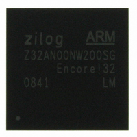
Z32AN00NW200SG Zilog, Z32AN00NW200SG Datasheet - Page 65

Z32AN00NW200SG
Manufacturer Part Number
Z32AN00NW200SG
Description
IC ARM922T MCU 200MHZ 256-BGA
Manufacturer
Zilog
Series
Encore!® 32r
Datasheet
1.Z32AN00NW200SG.pdf
(196 pages)
Specifications of Z32AN00NW200SG
Core Processor
ARM9
Core Size
16/32-Bit
Speed
200MHz
Connectivity
EBI/EMI, IrDA, SmartCard, SPI, UART/USART, USB OTG
Peripherals
DMA, LCD, Magnetic Card Reader, POR, PWM, WDT
Number Of I /o
76
Program Memory Type
ROMless
Ram Size
64K x 8
Voltage - Supply (vcc/vdd)
1.71 V ~ 3.6 V
Data Converters
A/D 4x10b
Oscillator Type
Internal
Operating Temperature
-40°C ~ 85°C
Package / Case
256-LBGA
For Use With
269-4713 - KIT DEV ENCORE 32 SERIES
Lead Free Status / RoHS Status
Lead free / RoHS Compliant
Eeprom Size
-
Program Memory Size
-
Other names
269-4717
Available stocks
Company
Part Number
Manufacturer
Quantity
Price
- Current page: 65 of 196
- Download datasheet (4Mb)
Z32AN Series Data Sheet
8.5
8.6
8.7
8.8
DS0200-003
Count-to-Zero Condition
When a channel AHB burst completes, the DMA controller checks to see if DMA_CNTN has been
decremented to 0. If so, there are two possible responses:
Chaining Buffers
The reload registers can be used for chaining buffers together. This allows the DMA to continue to service a
request without immediate processing from the CPU.
DMA_CRLDN.EN set to ‘1’, the channel remains active, the DMA_SRCN, DMA_DESTN, and DMA_CNTN is
loaded with values from the reload registers, and the DMA operation continues with the new DMA buffer. To
prevent improper operation, program the address before setting DMA_CRLDN.EN. The following fields
affect buffer chaining.
DMA Interrupts
The following registers and fields control DMA interrupts.
Channel Time-outs
Each channel can be configured to generate an interrupt when its associated request line is inactive. An
example of this feature is to determine an idle UART receive channel. The time-out mechanism consists of a
single global 24-bit pre-scalar and per-channel programmable 8-bit timers. The global pre-scalar has 3 taps:
a divide by 256, a divide by 64k, or a divide by 16M.
Each channel’s 8-bit timer increments using a tap chosen by DMA_CFGN.PS. DMA_CFGN.TO selects how
high the timer must count before generating an interrupt. The timer is reset whenever any of the following
conditions occurs:
Any timer can be disabled by clearing DMA_CFGN.PS to ‘00’. When all 8 channels are configured, the
global pre-scalar is disabled. Normally, the timer starts counting as soon as the channel is enabled and
DMA_CFGN.PS is non-zero. But if DMA_CFGN.WAIT is set, the timer starts counting only after the first
DMA request is received from the peripheral. The time-out period can be calculated using the following
equation:
With hclk frequency of 90 MHz and PS=10b and TO=100b, the time-out period is:
The following registers and fields control channel time-outs.
If DMA_CRLDN.EN is set, DMA_SRCN, DMA_DESTN, and DMA_CNTN are loaded from the
reload registers and the channel remains active using the newly loaded address/count values
and the previously programmed configuration values.
If DMA_STAN.RLOAD is cleared, the channel is disabled and DMA_STAN.EN is cleared to ‘0’.
DMA_SRLDN → All bits
DMA_DRLDN → All bits
DMA_CRLDN → EN, COUNT
DMA_CTRL → IENx
DMA_ISTAT → PENDx
DMA_CFGN → CTZ_IEN, STA_IEN
DMA_STAN → EN, IPEND, CTZ, RLOAD, BUS_ERR, TO
The DMA request line programmed for the channel is activated.
The channel is disabled for any reason (DMA_STAN.EN is zero).
DMA_CTRL → IENx
DMA_CFGN → PS, TO, WAIT
DMA_STAN → TO
When a count-to-zero condition occurs with
Page 52
Related parts for Z32AN00NW200SG
Image
Part Number
Description
Manufacturer
Datasheet
Request
R

Part Number:
Description:
Communication Controllers, ZILOG INTELLIGENT PERIPHERAL CONTROLLER (ZIP)
Manufacturer:
Zilog, Inc.
Datasheet:

Part Number:
Description:
KIT DEV FOR Z8 ENCORE 16K TO 64K
Manufacturer:
Zilog
Datasheet:

Part Number:
Description:
KIT DEV Z8 ENCORE XP 28-PIN
Manufacturer:
Zilog
Datasheet:

Part Number:
Description:
DEV KIT FOR Z8 ENCORE 8K/4K
Manufacturer:
Zilog
Datasheet:

Part Number:
Description:
KIT DEV Z8 ENCORE XP 28-PIN
Manufacturer:
Zilog
Datasheet:

Part Number:
Description:
DEV KIT FOR Z8 ENCORE 4K TO 8K
Manufacturer:
Zilog
Datasheet:

Part Number:
Description:
CMOS Z8 microcontroller. ROM 16 Kbytes, RAM 256 bytes, speed 16 MHz, 32 lines I/O, 3.0V to 5.5V
Manufacturer:
Zilog, Inc.
Datasheet:

Part Number:
Description:
Low-cost microcontroller. 512 bytes ROM, 61 bytes RAM, 8 MHz
Manufacturer:
Zilog, Inc.
Datasheet:

Part Number:
Description:
Z8 4K OTP Microcontroller
Manufacturer:
Zilog, Inc.
Datasheet:

Part Number:
Description:
CMOS SUPER8 ROMLESS MCU
Manufacturer:
Zilog, Inc.
Datasheet:

Part Number:
Description:
SL1866 CMOSZ8 OTP Microcontroller
Manufacturer:
Zilog, Inc.
Datasheet:

Part Number:
Description:
SL1866 CMOSZ8 OTP Microcontroller
Manufacturer:
Zilog, Inc.
Datasheet:

Part Number:
Description:
OTP (KB) = 1, RAM = 125, Speed = 12, I/O = 14, 8-bit Timers = 2, Comm Interfaces Other Features = Por, LV Protect, Voltage = 4.5-5.5V
Manufacturer:
Zilog, Inc.
Datasheet:

Part Number:
Description:
Manufacturer:
Zilog, Inc.
Datasheet:


