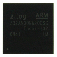
Z32AN00NW200SG Zilog, Z32AN00NW200SG Datasheet - Page 35

Z32AN00NW200SG
Manufacturer Part Number
Z32AN00NW200SG
Description
IC ARM922T MCU 200MHZ 256-BGA
Manufacturer
Zilog
Series
Encore!® 32r
Datasheet
1.Z32AN00NW200SG.pdf
(196 pages)
Specifications of Z32AN00NW200SG
Core Processor
ARM9
Core Size
16/32-Bit
Speed
200MHz
Connectivity
EBI/EMI, IrDA, SmartCard, SPI, UART/USART, USB OTG
Peripherals
DMA, LCD, Magnetic Card Reader, POR, PWM, WDT
Number Of I /o
76
Program Memory Type
ROMless
Ram Size
64K x 8
Voltage - Supply (vcc/vdd)
1.71 V ~ 3.6 V
Data Converters
A/D 4x10b
Oscillator Type
Internal
Operating Temperature
-40°C ~ 85°C
Package / Case
256-LBGA
For Use With
269-4713 - KIT DEV ENCORE 32 SERIES
Lead Free Status / RoHS Status
Lead free / RoHS Compliant
Eeprom Size
-
Program Memory Size
-
Other names
269-4717
Available stocks
Company
Part Number
Manufacturer
Quantity
Price
- Current page: 35 of 196
- Download datasheet (4Mb)
Z32AN Series Data Sheet
6.3
6.4
6.5
6.6
DS0200-003
Configuring the Interrupt Controller
Prior to configuring a particular channel, a number of settings must be made:
ISR Invocation
Below is an example of how the CPU, ARM Exception Table, INTC_VECN’s, and INTC_IVEC operate
together to invoke a Channel 1 ISR upon occurrence of a Channel 1 interrupt. Note the sequence of steps
listed at the bottom of the table. FIQ ISR invocation is almost identical, except that the CPU will read the
FIQ vector in the ARM exception table and this will cause INTC_FVEC to be read.
ISR Return from Interrupt
Before returning from an IRQ or FIQ interrupt, the ISR must write to INTC_IEND or INTC_FEND. The data
written is not important and is discarded. After this write is done, the final instruction of an IRQ or FIQ ISR
must restore the PC and CPSR. When using nested interrupts, the interrupts should be disabled before
writing to INTC_IEND.
Interrupt Nesting
The IRQ processor nests interrupts (preemption of an ISR by a higher priority interrupt). The FIQ processor
cannot nest interrupts. Active and enabled interrupt channels with a higher programmed priority always
result in an interrupt being passed on to the CPU (via either IRQ or FIQ). To utilize this feature, software
must clear the “I” bit of the ARM922T CPSR register within the ISR to re-enable interrupts, thereby
“enabling” interrupt nesting. More information can be found in Chapter A2, Programmer’s Model of the ARM
Architecture Reference Manual.
To keep track of the nested interrupts, the IRQ Processor contains a priority stack. Since there are 8
priorities, the stack is 8 deep. A read of INTC_IVEC pushes the stack. A write to INTC_IEND pops the stack.
During the time between push and pop, interrupts of the same or lower priority are masked.
programmer’s responsibility is to ensure there is a write to INTC_IEND every read of INTC_IVEC.
1.
2.
3.
4.
1.
2.
3.
4.
5.
The ARM exception table should be set up. This typically is done by remapping the SRAM to
appear at the bottom of memory and placing the following ARM instruction at locations
0x00000018 (IRQ Vector) and 0x0000001C (FIQ Vector) as shown in the example below:
o
o
INTC_DFLT should be initialized to the address of an error handling ISR. This is to provide a
vector for error handling in the case where INTC_IVEC or INTC_FVEC are read when there is
no interrupt active. This usually indicates a spurious interrupt or a software error.
Set up any or all of the interrupt channels. The following registers and fields are used:
o
o
o
The “I” and/or “F” bits of the ARM922T CPSR register should be cleared to enable IRQ and/or
FIQ interrupts.
IRQ is set up:
o
o
o
An active IRQ causes the CPU to execute the IRQ vector instruction at 00000018h:
o
LDR instruction causes CPU to read memory location FFFFFF00h (INTC_IVEC).
INTC provides the vector of the highest priority active interrupt (00000180h).
CPU move the data 00000180h) into PC. Program execution then continues at this address.
LDR PC, [PC,#0xFFFFFF00 - (0x18+8)] ; IRQ Vector (located at A=0x0018)
LDR PC, [PC,#0xFFFFFF04 - (0x1C+8)] ; FIQ Vector (located at A=0x001C)
INTC_CFGN → IRQ_FIQ, PRI
INT_VEC_N → All Bits
INTC_EN → Bit “N”
The IRQ Vector, INTC_VEC_1 are initialized and the Channel 1 ISR is located as shown
above.
Channel 1 is configured as an IRQ (as opposed to an FIQ), programmed to have the
highest priority, and enabled.
A channel 1 interrupt enters the INTC, which is passed on to the CPU by activating IRQ.
LDR PC, [PC, #0xFFFFFF00-(0x18+8)]
Page 22
The
Related parts for Z32AN00NW200SG
Image
Part Number
Description
Manufacturer
Datasheet
Request
R

Part Number:
Description:
Communication Controllers, ZILOG INTELLIGENT PERIPHERAL CONTROLLER (ZIP)
Manufacturer:
Zilog, Inc.
Datasheet:

Part Number:
Description:
KIT DEV FOR Z8 ENCORE 16K TO 64K
Manufacturer:
Zilog
Datasheet:

Part Number:
Description:
KIT DEV Z8 ENCORE XP 28-PIN
Manufacturer:
Zilog
Datasheet:

Part Number:
Description:
DEV KIT FOR Z8 ENCORE 8K/4K
Manufacturer:
Zilog
Datasheet:

Part Number:
Description:
KIT DEV Z8 ENCORE XP 28-PIN
Manufacturer:
Zilog
Datasheet:

Part Number:
Description:
DEV KIT FOR Z8 ENCORE 4K TO 8K
Manufacturer:
Zilog
Datasheet:

Part Number:
Description:
CMOS Z8 microcontroller. ROM 16 Kbytes, RAM 256 bytes, speed 16 MHz, 32 lines I/O, 3.0V to 5.5V
Manufacturer:
Zilog, Inc.
Datasheet:

Part Number:
Description:
Low-cost microcontroller. 512 bytes ROM, 61 bytes RAM, 8 MHz
Manufacturer:
Zilog, Inc.
Datasheet:

Part Number:
Description:
Z8 4K OTP Microcontroller
Manufacturer:
Zilog, Inc.
Datasheet:

Part Number:
Description:
CMOS SUPER8 ROMLESS MCU
Manufacturer:
Zilog, Inc.
Datasheet:

Part Number:
Description:
SL1866 CMOSZ8 OTP Microcontroller
Manufacturer:
Zilog, Inc.
Datasheet:

Part Number:
Description:
SL1866 CMOSZ8 OTP Microcontroller
Manufacturer:
Zilog, Inc.
Datasheet:

Part Number:
Description:
OTP (KB) = 1, RAM = 125, Speed = 12, I/O = 14, 8-bit Timers = 2, Comm Interfaces Other Features = Por, LV Protect, Voltage = 4.5-5.5V
Manufacturer:
Zilog, Inc.
Datasheet:

Part Number:
Description:
Manufacturer:
Zilog, Inc.
Datasheet:


