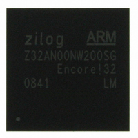
Z32AN00NW200SG Zilog, Z32AN00NW200SG Datasheet - Page 137

Z32AN00NW200SG
Manufacturer Part Number
Z32AN00NW200SG
Description
IC ARM922T MCU 200MHZ 256-BGA
Manufacturer
Zilog
Series
Encore!® 32r
Datasheet
1.Z32AN00NW200SG.pdf
(196 pages)
Specifications of Z32AN00NW200SG
Core Processor
ARM9
Core Size
16/32-Bit
Speed
200MHz
Connectivity
EBI/EMI, IrDA, SmartCard, SPI, UART/USART, USB OTG
Peripherals
DMA, LCD, Magnetic Card Reader, POR, PWM, WDT
Number Of I /o
76
Program Memory Type
ROMless
Ram Size
64K x 8
Voltage - Supply (vcc/vdd)
1.71 V ~ 3.6 V
Data Converters
A/D 4x10b
Oscillator Type
Internal
Operating Temperature
-40°C ~ 85°C
Package / Case
256-LBGA
For Use With
269-4713 - KIT DEV ENCORE 32 SERIES
Lead Free Status / RoHS Status
Lead free / RoHS Compliant
Eeprom Size
-
Program Memory Size
-
Other names
269-4717
Available stocks
Company
Part Number
Manufacturer
Quantity
Price
- Current page: 137 of 196
- Download datasheet (4Mb)
Z32AN Series Data Sheet
16.3.2.3
16.3.2.4
DS0200-003
In this mode, the timer counts time outs on the cascade input that comes from the previous timer. Timers 4
through 8 are sequentially tied from cascade output to cascade input and Timer 8’s cascade output ties to
Timer 4 cascade input. Any number of timers can be put in the cascade chain and the first timer can be any
one of the 5 timers. The first timer in the chain can be set up to be in One-Shot, Continuous or Compare
mode to have an output occur for the next cascade input. The rest of the timers in the chain must be in
Counter/Cascade mode. In this mode, the pre-scalar is ignored.
For the timers using this mode in the chain, upon reaching TxR, the timer generates an interrupt, the count
value in Tx is reset to 00000001h and counting resumes. To use the full 32-bits for the timer, 00000000h
should be written to Tx. The steps for configuring a timer for Counter mode and initiating the count are as
follows:
The number of Cascade Input transitions since the timer start is given by the following equation:
In this mode, Tx counts to TxR via hclk. Upon reaching TxR, an interrupt is generated, Tx is reset to
00000001h, and counting resumes. When the Timer reaches FFFFFFFFh, the timer rolls to 00000000h and
continues counting. The steps for configuring a timer for this mode are:
The Compare time is given by the following equation:
Counter/Cascade Mode
Compare Mode
1.
2.
3.
4.
5.
1.
2.
3.
4.
Clear TxCTL.TEN and write TxCTL.TMODE to “010”.
Write Tx to set the starting count value. This affects the first pass. After reaching TxR, counting
begins at the reset value of 00000001h.
Write TxR.
If desired, enable the timer interrupt (via the Interrupt Mask Register in the Interrupt Controller)
and set the timer interrupt priority (by writing to the appropriate Configuration Table Register in
the Interrupt Controller herein).
Set TxCTL.TEN.
Clear TxCTL.TEN and write TxCTL.TMODE to “101”, and write TxCTL.PRES.
Write Tx and TxR.
If desired, enable the timer interrupt (via the Interrupt Mask Register in the Interrupt Controller)
and set the timer interrupt priority (by writing to the appropriate Configuration Table Register in
the Interrupt Controller herein).
Set TxCTL.TEN
Page 124
Related parts for Z32AN00NW200SG
Image
Part Number
Description
Manufacturer
Datasheet
Request
R

Part Number:
Description:
Communication Controllers, ZILOG INTELLIGENT PERIPHERAL CONTROLLER (ZIP)
Manufacturer:
Zilog, Inc.
Datasheet:

Part Number:
Description:
KIT DEV FOR Z8 ENCORE 16K TO 64K
Manufacturer:
Zilog
Datasheet:

Part Number:
Description:
KIT DEV Z8 ENCORE XP 28-PIN
Manufacturer:
Zilog
Datasheet:

Part Number:
Description:
DEV KIT FOR Z8 ENCORE 8K/4K
Manufacturer:
Zilog
Datasheet:

Part Number:
Description:
KIT DEV Z8 ENCORE XP 28-PIN
Manufacturer:
Zilog
Datasheet:

Part Number:
Description:
DEV KIT FOR Z8 ENCORE 4K TO 8K
Manufacturer:
Zilog
Datasheet:

Part Number:
Description:
CMOS Z8 microcontroller. ROM 16 Kbytes, RAM 256 bytes, speed 16 MHz, 32 lines I/O, 3.0V to 5.5V
Manufacturer:
Zilog, Inc.
Datasheet:

Part Number:
Description:
Low-cost microcontroller. 512 bytes ROM, 61 bytes RAM, 8 MHz
Manufacturer:
Zilog, Inc.
Datasheet:

Part Number:
Description:
Z8 4K OTP Microcontroller
Manufacturer:
Zilog, Inc.
Datasheet:

Part Number:
Description:
CMOS SUPER8 ROMLESS MCU
Manufacturer:
Zilog, Inc.
Datasheet:

Part Number:
Description:
SL1866 CMOSZ8 OTP Microcontroller
Manufacturer:
Zilog, Inc.
Datasheet:

Part Number:
Description:
SL1866 CMOSZ8 OTP Microcontroller
Manufacturer:
Zilog, Inc.
Datasheet:

Part Number:
Description:
OTP (KB) = 1, RAM = 125, Speed = 12, I/O = 14, 8-bit Timers = 2, Comm Interfaces Other Features = Por, LV Protect, Voltage = 4.5-5.5V
Manufacturer:
Zilog, Inc.
Datasheet:

Part Number:
Description:
Manufacturer:
Zilog, Inc.
Datasheet:


