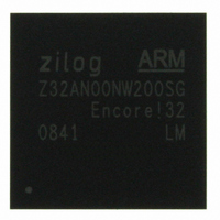
Z32AN00NW200SG Zilog, Z32AN00NW200SG Datasheet - Page 58

Z32AN00NW200SG
Manufacturer Part Number
Z32AN00NW200SG
Description
IC ARM922T MCU 200MHZ 256-BGA
Manufacturer
Zilog
Series
Encore!® 32r
Datasheet
1.Z32AN00NW200SG.pdf
(196 pages)
Specifications of Z32AN00NW200SG
Core Processor
ARM9
Core Size
16/32-Bit
Speed
200MHz
Connectivity
EBI/EMI, IrDA, SmartCard, SPI, UART/USART, USB OTG
Peripherals
DMA, LCD, Magnetic Card Reader, POR, PWM, WDT
Number Of I /o
76
Program Memory Type
ROMless
Ram Size
64K x 8
Voltage - Supply (vcc/vdd)
1.71 V ~ 3.6 V
Data Converters
A/D 4x10b
Oscillator Type
Internal
Operating Temperature
-40°C ~ 85°C
Package / Case
256-LBGA
For Use With
269-4713 - KIT DEV ENCORE 32 SERIES
Lead Free Status / RoHS Status
Lead free / RoHS Compliant
Eeprom Size
-
Program Memory Size
-
Other names
269-4717
Available stocks
Company
Part Number
Manufacturer
Quantity
Price
- Current page: 58 of 196
- Download datasheet (4Mb)
Z32AN Series Data Sheet
7.4.1.6
DS0200-003
There are 10 memory controller chip select configuration registers. The above table lists the offsets, and the
table below describes the bits in each register.
31:11
10:08
MEMC_CFGn – Memory Controller nCS[“n”] Configuration Registers
Bits
07
06
05
04
03
02
01
00
Type
RW
RW
RW
RW
RW
RW
RW
RW
RO
RO
Reset
000
0
0
0
0
0
0
0
0
1
Offset
01Ch
014h
018h
020h
024h
Description
Reserved
Page Boundary (PAGE_BDRY): Specifies the boundary limit for sync or async burst
reads. This is defined in terms of the least significant AHB address bit which must
remain constant for the burst to continue.
Extend (EXT): When set, CS1 or CS3 becomes MA[24] and CS0 address space is
32MB. When cleared, CS1 or CS3 used normally. Note: Can use CS1 only if there is no
SDRAM.
Reserved
Page Mode (PAGE_EN): When set, enables asynchronous page reads for this device.
FLCLK Based Timing Enable (FLCLK_BTEN): When set, enables the clock divider
for this external device. Uses the flclk divider to provide longer clock cycles for slow
peripherals. When cleared, flclk Timing disabled.
READY Pin Polarity (RDY_POL): When set, ‘1’ means ready. When cleared, VSS
means ready.
READY Pin Enable (RDY_EN): When set, READY indicates cycle completion. When
cleared, READY pin ignored
Byte Control Style (BYTE_STYLE): Specifies the style of the control bits used. This
is used to provide a seamless solution for interfaces:
Data Bus Width (WDTH): When cleared, external device width is 8 bits. When set,
external device width is 16-bits.
000: A[2]
001: A[3]
010: A[4]
011: A[5]
100: A[6]
101: A[7]
16-bit using 2xWE and no BE, 16-bit using 1xWE and 2xBE, 8-bit using 1xWE
When cleared, nWEU=nWEU, nWEL=nWEL, A[0] = unused, held low
When set, nWEU=nBEU, nWEL=nEW, A[0] = nBEL
8-bit device:
When cleared, nWEU= unused, held high, nWEL=nWE, A[0] = A0
When set, nWEU=nBE, nWEL=nWE, A[0] = A0
and no BE, 8-bit using 1xWE and 1xBE16-bit device:
Chip Select
0
1
2
3
4
Offset
02Ch
028h
030h
034h
038h
Chip Select
5
6
7
8
9
Page 45
Related parts for Z32AN00NW200SG
Image
Part Number
Description
Manufacturer
Datasheet
Request
R

Part Number:
Description:
Communication Controllers, ZILOG INTELLIGENT PERIPHERAL CONTROLLER (ZIP)
Manufacturer:
Zilog, Inc.
Datasheet:

Part Number:
Description:
KIT DEV FOR Z8 ENCORE 16K TO 64K
Manufacturer:
Zilog
Datasheet:

Part Number:
Description:
KIT DEV Z8 ENCORE XP 28-PIN
Manufacturer:
Zilog
Datasheet:

Part Number:
Description:
DEV KIT FOR Z8 ENCORE 8K/4K
Manufacturer:
Zilog
Datasheet:

Part Number:
Description:
KIT DEV Z8 ENCORE XP 28-PIN
Manufacturer:
Zilog
Datasheet:

Part Number:
Description:
DEV KIT FOR Z8 ENCORE 4K TO 8K
Manufacturer:
Zilog
Datasheet:

Part Number:
Description:
CMOS Z8 microcontroller. ROM 16 Kbytes, RAM 256 bytes, speed 16 MHz, 32 lines I/O, 3.0V to 5.5V
Manufacturer:
Zilog, Inc.
Datasheet:

Part Number:
Description:
Low-cost microcontroller. 512 bytes ROM, 61 bytes RAM, 8 MHz
Manufacturer:
Zilog, Inc.
Datasheet:

Part Number:
Description:
Z8 4K OTP Microcontroller
Manufacturer:
Zilog, Inc.
Datasheet:

Part Number:
Description:
CMOS SUPER8 ROMLESS MCU
Manufacturer:
Zilog, Inc.
Datasheet:

Part Number:
Description:
SL1866 CMOSZ8 OTP Microcontroller
Manufacturer:
Zilog, Inc.
Datasheet:

Part Number:
Description:
SL1866 CMOSZ8 OTP Microcontroller
Manufacturer:
Zilog, Inc.
Datasheet:

Part Number:
Description:
OTP (KB) = 1, RAM = 125, Speed = 12, I/O = 14, 8-bit Timers = 2, Comm Interfaces Other Features = Por, LV Protect, Voltage = 4.5-5.5V
Manufacturer:
Zilog, Inc.
Datasheet:

Part Number:
Description:
Manufacturer:
Zilog, Inc.
Datasheet:


