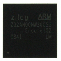
Z32AN00NW200SG Zilog, Z32AN00NW200SG Datasheet - Page 138

Z32AN00NW200SG
Manufacturer Part Number
Z32AN00NW200SG
Description
IC ARM922T MCU 200MHZ 256-BGA
Manufacturer
Zilog
Series
Encore!® 32r
Datasheet
1.Z32AN00NW200SG.pdf
(196 pages)
Specifications of Z32AN00NW200SG
Core Processor
ARM9
Core Size
16/32-Bit
Speed
200MHz
Connectivity
EBI/EMI, IrDA, SmartCard, SPI, UART/USART, USB OTG
Peripherals
DMA, LCD, Magnetic Card Reader, POR, PWM, WDT
Number Of I /o
76
Program Memory Type
ROMless
Ram Size
64K x 8
Voltage - Supply (vcc/vdd)
1.71 V ~ 3.6 V
Data Converters
A/D 4x10b
Oscillator Type
Internal
Operating Temperature
-40°C ~ 85°C
Package / Case
256-LBGA
For Use With
269-4713 - KIT DEV ENCORE 32 SERIES
Lead Free Status / RoHS Status
Lead free / RoHS Compliant
Eeprom Size
-
Program Memory Size
-
Other names
269-4717
Available stocks
Company
Part Number
Manufacturer
Quantity
Price
- Current page: 138 of 196
- Download datasheet (4Mb)
Z32AN Series Data Sheet
16.3.3 UART Mode
16.3.4 Reading the Timer Count Values
DS0200-003
In UART mode, RxD of UART0, UART1, and UART2 are connected to timer inputs 4,5,6. Timer mode 7
(111b) can be used to measure the ASCII CR character 0x0D (13). The timer should be enabled to begin
searching for an auto baud character. The timer enable bit will clear once an auto baud character has been
measured.
To measure the auto baud character, the timer reload register should be setup with the maximum character
time. This allows the timer to automatically reject break conditions which can be used to reset the serial
interface. The timer measures the duration of 8 bit times. It starts measuring at the rising edge ending the
start bit to the rising edge beginning the stop bit.
To obtain the baud rate, the timer count should be divided by 8 (shifted right by 3) to get the individual bit
time. The bit count then needs to be divided by 16 (shifted right by 4) to obtain the baud rate. Rounding
should be done to achieve maximum resolution. Since the timer is preset to 1, the resulting character count
is one larger than the actual character time. The baud rate can be calculated as follows:
Since the auto baud timer automatically rejects baud rates too slow, a break condition can be used as a way
to reset the serial line. When software detects a break condition, it can place the timer in auto baud mode.
The auto baud search hardware will wait until the RxD pin is idle (high) before beginning an auto baud
measurement. Once the auto baud hardware sees the RxD pin go low for the start bit, it starts the counter. If
the timer overflows, it assumes a break condition was detected and will reset. The timer will wait for the RxD
pin to go high again before searching for another start bit character.
When the auto baud timer sees the rising edge at the end of the start bit, it will reset the timer and begin the
character measurement. It will stop counting once it sees the beginning of the stop bit which is two rising
edges of the RxD line later. If the counter overflows during this time, it automatically resets and waits for the
RxD line to go idle again before searching for another start bit character. If the counter does not overflow,
the timer enable bit will clear indicating an auto baud character was measured successfully. Figure 16-2
contains an illustration on auto baud timing.
The current count value in the timers can be read while the timer is counting (TEN = “1”). The read has no
effect on timer operation.
Figure 16-2: Auto baud Timing Diagram
Page 125
Related parts for Z32AN00NW200SG
Image
Part Number
Description
Manufacturer
Datasheet
Request
R

Part Number:
Description:
Communication Controllers, ZILOG INTELLIGENT PERIPHERAL CONTROLLER (ZIP)
Manufacturer:
Zilog, Inc.
Datasheet:

Part Number:
Description:
KIT DEV FOR Z8 ENCORE 16K TO 64K
Manufacturer:
Zilog
Datasheet:

Part Number:
Description:
KIT DEV Z8 ENCORE XP 28-PIN
Manufacturer:
Zilog
Datasheet:

Part Number:
Description:
DEV KIT FOR Z8 ENCORE 8K/4K
Manufacturer:
Zilog
Datasheet:

Part Number:
Description:
KIT DEV Z8 ENCORE XP 28-PIN
Manufacturer:
Zilog
Datasheet:

Part Number:
Description:
DEV KIT FOR Z8 ENCORE 4K TO 8K
Manufacturer:
Zilog
Datasheet:

Part Number:
Description:
CMOS Z8 microcontroller. ROM 16 Kbytes, RAM 256 bytes, speed 16 MHz, 32 lines I/O, 3.0V to 5.5V
Manufacturer:
Zilog, Inc.
Datasheet:

Part Number:
Description:
Low-cost microcontroller. 512 bytes ROM, 61 bytes RAM, 8 MHz
Manufacturer:
Zilog, Inc.
Datasheet:

Part Number:
Description:
Z8 4K OTP Microcontroller
Manufacturer:
Zilog, Inc.
Datasheet:

Part Number:
Description:
CMOS SUPER8 ROMLESS MCU
Manufacturer:
Zilog, Inc.
Datasheet:

Part Number:
Description:
SL1866 CMOSZ8 OTP Microcontroller
Manufacturer:
Zilog, Inc.
Datasheet:

Part Number:
Description:
SL1866 CMOSZ8 OTP Microcontroller
Manufacturer:
Zilog, Inc.
Datasheet:

Part Number:
Description:
OTP (KB) = 1, RAM = 125, Speed = 12, I/O = 14, 8-bit Timers = 2, Comm Interfaces Other Features = Por, LV Protect, Voltage = 4.5-5.5V
Manufacturer:
Zilog, Inc.
Datasheet:

Part Number:
Description:
Manufacturer:
Zilog, Inc.
Datasheet:


