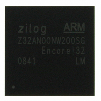
Z32AN00NW200SG Zilog, Z32AN00NW200SG Datasheet - Page 5

Z32AN00NW200SG
Manufacturer Part Number
Z32AN00NW200SG
Description
IC ARM922T MCU 200MHZ 256-BGA
Manufacturer
Zilog
Series
Encore!® 32r
Datasheet
1.Z32AN00NW200SG.pdf
(196 pages)
Specifications of Z32AN00NW200SG
Core Processor
ARM9
Core Size
16/32-Bit
Speed
200MHz
Connectivity
EBI/EMI, IrDA, SmartCard, SPI, UART/USART, USB OTG
Peripherals
DMA, LCD, Magnetic Card Reader, POR, PWM, WDT
Number Of I /o
76
Program Memory Type
ROMless
Ram Size
64K x 8
Voltage - Supply (vcc/vdd)
1.71 V ~ 3.6 V
Data Converters
A/D 4x10b
Oscillator Type
Internal
Operating Temperature
-40°C ~ 85°C
Package / Case
256-LBGA
For Use With
269-4713 - KIT DEV ENCORE 32 SERIES
Lead Free Status / RoHS Status
Lead free / RoHS Compliant
Eeprom Size
-
Program Memory Size
-
Other names
269-4717
Available stocks
Company
Part Number
Manufacturer
Quantity
Price
Z32AN Series Data Sheet
DS0200-003
Chapter 1: Pin Description ............................................................................................. 1
Chapter 2: Reset..............................................................................................................7
Chapter 3: System Clocks and Power Management ................................................. 8
Chapter 4: ARM922T Core and Embedded ICE ......................................................... 16
Chapter 5: Memory Organization ............................................................................... 17
1.1 System Pins ............................................................................................................................................. 1
1.2 External Bus Interface........................................................................................................................... 1
1.3 Secondary External Bus Interface ...................................................................................................... 1
1.4 External DMA Interface........................................................................................................................ 2
1.5 Timer/Counter........................................................................................................................................ 2
1.6 RTC........................................................................................................................................................... 2
1.7 UARTs ....................................................................................................................................................... 2
1.8 SPI............................................................................................................................................................. 3
1.9 USB Interface ......................................................................................................................................... 3
1.10 SmartCard Interface ............................................................................................................................ 4
1.11 LCD Display Interface .......................................................................................................................... 4
1.12 Dedicated General Purpose I/O......................................................................................................... 4
1.13 ADC......................................................................................................................................................... 4
1.14 Magnetic Card Reader ....................................................................................................................... 5
1.15 JTAG ........................................................................................................................................................ 5
1.16 Power ...................................................................................................................................................... 5
1.17 Pin Assignments, 256 BGA Package.................................................................................................. 6
2.1 System Reset .......................................................................................................................................... 7
2.2 Hard Reset.............................................................................................................................................. 7
2.3 Peripheral Reset .................................................................................................................................... 7
3.1 Power Modes......................................................................................................................................... 9
3.2 Wake Mechanisms ............................................................................................................................... 9
3.3 Main Oscillator External Circuits ....................................................................................................... 10
3.4 System Clocking Notes ...................................................................................................................... 10
3.5 PMU Registers: (Base → FFFFE000h).................................................................................................. 11
5.1 Memory Map ....................................................................................................................................... 17
1.7.1
1.7.2
1.7.3
1.8.1
1.8.2
1.10.1 Port 0....................................................................................................................................4
1.10.2 Port 1....................................................................................................................................4
1.10.3 SmartCard SPI Interface ....................................................................................................4
3.1.1
3.1.1
3.1.2
3.1.3
3.5.1
3.5.2
3.5.3
3.5.4
3.5.5
3.5.6
UART0...................................................................................................................................2
UART1...................................................................................................................................2
UART2...................................................................................................................................3
Port 0....................................................................................................................................3
Port 1....................................................................................................................................3
HALT - ARM922 Wait for Interrupt ......................................................................................9
IDLE ......................................................................................................................................9
STOP .....................................................................................................................................9
Battery Back Up ..................................................................................................................9
Offset 000h: PMUPLL – PMU PLL Register.........................................................................11
Offset 004h: PMUCLK – PMU Clock Control Register .....................................................12
Offset 008h: PMUCKEN – PMU Clock Enable Register...................................................13
Offset 00Ch: PMURESET – PMU Reset Register................................................................14
Offset 014h: PMUID – PMU ID Register ............................................................................14
Offset 01Ch: PMUCFG – PMU Configuration Register ...................................................15
Table of Contents
Page iii


