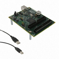
DK-DEV-5M570ZN Altera, DK-DEV-5M570ZN Datasheet - Page 115

DK-DEV-5M570ZN
Manufacturer Part Number
DK-DEV-5M570ZN
Description
KIT DEV MAX V 5M570Z
Manufacturer
Altera
Series
MAX® Vr
Type
CPLDr
Datasheets
1.DK-DEV-5M570ZN.pdf
(30 pages)
2.DK-DEV-5M570ZN.pdf
(2 pages)
3.DK-DEV-5M570ZN.pdf
(30 pages)
4.DK-DEV-5M570ZN.pdf
(164 pages)
5.DK-DEV-5M570ZN.pdf
(24 pages)
Specifications of DK-DEV-5M570ZN
Contents
Board, Cable(s), Software and Documentation
Silicon Manufacturer
Altera
Core Architecture
CPLD
Core Sub-architecture
MAX
Silicon Core Number
5M
Silicon Family Name
MAX V
Kit Contents
MAX V CPLD Development Board, USB Cable
Rohs Compliant
Yes
Lead Free Status / RoHS Status
Lead free / RoHS Compliant
For Use With/related Products
5M570ZF256
Lead Free Status / Rohs Status
Compliant
Other names
544-2722
Available stocks
Company
Part Number
Manufacturer
Quantity
Price
Chapter 7: User Flash Memory in MAX V Devices
Software Support for UFM Block
Software Support for UFM Block
January 2011 Altera Corporation
Inter-Integrated Circuit
The Altera Quartus II software includes sophisticated tools that fully utilize the
advantages of the UFM block in MAX V devices, while maintaining simple, easy-to-
use procedures that accelerate the design process. The following section describes
how the ALTUFM megafunction supports a simple design methodology for
instantiating standard interface protocols for the UFM block, such as:
■
■
■
■
This section includes the megafunction symbol, the input and output ports, and a
description of the MegaWizard Plug-In Manager options. Refer to Quartus II Help for
the ALTUFM megafunction Altera Hardware Description Language (AHDL)
functional prototypes (applicable to Verilog HDL), VHDL component declarations,
and parameter descriptions. You can access this megafunction from the Memory
Compiler directory on page 2a of the MegaWizard Plug-In Manager.
The ALTUFM MegaWizard Plug-In Manager has separate pages that apply to the
MAX V UFM block. During compilation, the Quartus II Compiler verifies the
ALTUFM parameters selected against the available logic array interface options, and
any specific assignments.
Inter-Integrated Circuit (I
only two bus lines: a serial data/address line (SDA), and a serial clock line (SCL).
Each device connected to the I
I
initiating a data transfer can be connected to it, which allows masters to function as
transmitters or receivers.
The ALTUFM_I2C megafunction features a serial, 8-bit bidirectional data transfer up
to 100 Kbits per second. With the ALTUFM_I2C megafunction, the MAX V UFM and
logic can be configured as a slave device for the I
I
The Quartus II software supports four different memory sizes:
■
■
■
■
I
The following defines the characteristics of the I
■
2
2
2
C bus is a multi-master bus where more than one integrated circuit (IC) capable of
C interface is designed to function similar to I
C Protocol
I
SPI
Parallel
None (Altera Serial Interface)
(128 × 8) 1 Kbits
(256 × 8) 2 Kbits
(512 × 8) 4 Kbits
(1,024 × 8) 8 Kbits
Only two bus lines are required: SDA and SCL. Both SDA and SCL are
bidirectional lines that remain high when the bus is free.
2
C
2
C) is a bidirectional two-wire interface protocol, requiring
2
C bus is software addressable by a unique address. The
2
2
C serial EEPROMs.
2
C bus protocol:
C bus. The ALTUFM megafunction’s
MAX V Device Handbook
7–13


