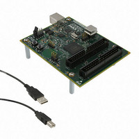
DK-DEV-5M570ZN Altera, DK-DEV-5M570ZN Datasheet - Page 31

DK-DEV-5M570ZN
Manufacturer Part Number
DK-DEV-5M570ZN
Description
KIT DEV MAX V 5M570Z
Manufacturer
Altera
Series
MAX® Vr
Type
CPLDr
Datasheets
1.DK-DEV-5M570ZN.pdf
(30 pages)
2.DK-DEV-5M570ZN.pdf
(2 pages)
3.DK-DEV-5M570ZN.pdf
(30 pages)
4.DK-DEV-5M570ZN.pdf
(164 pages)
5.DK-DEV-5M570ZN.pdf
(24 pages)
Specifications of DK-DEV-5M570ZN
Contents
Board, Cable(s), Software and Documentation
Silicon Manufacturer
Altera
Core Architecture
CPLD
Core Sub-architecture
MAX
Silicon Core Number
5M
Silicon Family Name
MAX V
Kit Contents
MAX V CPLD Development Board, USB Cable
Rohs Compliant
Yes
Lead Free Status / RoHS Status
Lead free / RoHS Compliant
For Use With/related Products
5M570ZF256
Lead Free Status / Rohs Status
Compliant
Other names
544-2722
Available stocks
Company
Part Number
Manufacturer
Quantity
Price
- DK-DEV-5M570ZN PDF datasheet
- DK-DEV-5M570ZN PDF datasheet #2
- DK-DEV-5M570ZN PDF datasheet #3
- DK-DEV-5M570ZN PDF datasheet #4
- DK-DEV-5M570ZN PDF datasheet #5
- Current page: 31 of 164
- Download datasheet (5Mb)
Chapter 2: MAX V Architecture
Global Signals
Global Signals
December 2010 Altera Corporation
Each MAX V device has four dual-purpose dedicated clock pins (GCLK[3..0], two
pins on the left side and two pins on the right side) that drive the global clock network
for clocking, as shown in
they are not used to drive the global clock network.
The four global clock lines in the global clock network drive throughout the entire
device. The global clock network can provide clocks for all resources within the
device including LEs, LAB local interconnect, IOEs, and the UFM block. The global
clock lines can also be used for global control signals, such as clock enables,
synchronous or asynchronous clears, presets, output enables, or protocol control
signals such as TRDY and IRDY for the PCI I/O standard. Internal logic can drive the
global clock network for internally-generated global clocks and control signals.
Figure 2–13
Figure 2–13. Global Clock Generation
Note to
(1) Any I/O pin can use a MultiTrack interconnect to route as a logic array-generated global clock signal.
The global clock network drives to individual LAB column signals, LAB column
clocks [3..0], that span an entire LAB column from the top to the bottom of the
device. Unused global clocks or control signals in an LAB column are turned off at the
LAB column clock buffers shown in
multiplexed down to two LAB clock signals and one LAB clear signal. Other control
signal types route from the global clock network into the LAB local interconnect. For
more information, refer to
Figure 2–13
shows the various sources that drive the global clock network.
:
Logic Array(1)
GCLK0
GCLK1
GCLK2
GCLK3
Figure
“LAB Control Signals” on page
2–13. These four pins can also be used as GPIOs if
4
Figure
2–14. The LAB column clocks [3..0] are
4
Global Clock
Network
2–6.
MAX V Device Handbook
2–19
Related parts for DK-DEV-5M570ZN
Image
Part Number
Description
Manufacturer
Datasheet
Request
R

Part Number:
Description:
KIT DEV ARRIA II GX FPGA 2AGX125
Manufacturer:
Altera
Datasheet:

Part Number:
Description:
KIT DEV CYCLONE III LS EP3CLS200
Manufacturer:
Altera
Datasheet:

Part Number:
Description:
KIT DEV STRATIX IV FPGA 4SE530
Manufacturer:
Altera
Datasheet:

Part Number:
Description:
KIT DEV FPGA 2AGX260 W/6.375G TX
Manufacturer:
Altera
Datasheet:

Part Number:
Description:
KIT DEV STRATIX V FPGA 5SGXEA7
Manufacturer:
Altera
Datasheet:

Part Number:
Description:
KIT DEVELOPMENT STRATIX III
Manufacturer:
Altera
Datasheet:

Part Number:
Description:
KIT DEVELOPMENT STRATIX IV
Manufacturer:
Altera
Datasheet:

Part Number:
Description:
KIT DEV ARRIA GX 1AGX60N
Manufacturer:
Altera
Datasheet:

Part Number:
Description:
KIT STARTER CYCLONE IV GX
Manufacturer:
Altera
Datasheet:

Part Number:
Description:
KIT DEVELOPMENT STRATIX IV
Manufacturer:
Altera
Datasheet:

Part Number:
Description:
CPLD, EP610 Family, ECMOS Process, 300 Gates, 16 Macro Cells, 16 Reg., 16 User I/Os, 5V Supply, 35 Speed Grade, 24DIP
Manufacturer:
Altera Corporation
Datasheet:

Part Number:
Description:
CPLD, EP610 Family, ECMOS Process, 300 Gates, 16 Macro Cells, 16 Reg., 16 User I/Os, 5V Supply, 15 Speed Grade, 24DIP
Manufacturer:
Altera Corporation
Datasheet:


