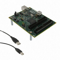
DK-DEV-5M570ZN Altera, DK-DEV-5M570ZN Datasheet - Page 125

DK-DEV-5M570ZN
Manufacturer Part Number
DK-DEV-5M570ZN
Description
KIT DEV MAX V 5M570Z
Manufacturer
Altera
Series
MAX® Vr
Type
CPLDr
Datasheets
1.DK-DEV-5M570ZN.pdf
(30 pages)
2.DK-DEV-5M570ZN.pdf
(2 pages)
3.DK-DEV-5M570ZN.pdf
(30 pages)
4.DK-DEV-5M570ZN.pdf
(164 pages)
5.DK-DEV-5M570ZN.pdf
(24 pages)
Specifications of DK-DEV-5M570ZN
Contents
Board, Cable(s), Software and Documentation
Silicon Manufacturer
Altera
Core Architecture
CPLD
Core Sub-architecture
MAX
Silicon Core Number
5M
Silicon Family Name
MAX V
Kit Contents
MAX V CPLD Development Board, USB Cable
Rohs Compliant
Yes
Lead Free Status / RoHS Status
Lead free / RoHS Compliant
For Use With/related Products
5M570ZF256
Lead Free Status / Rohs Status
Compliant
Other names
544-2722
Available stocks
Company
Part Number
Manufacturer
Quantity
Price
- DK-DEV-5M570ZN PDF datasheet
- DK-DEV-5M570ZN PDF datasheet #2
- DK-DEV-5M570ZN PDF datasheet #3
- DK-DEV-5M570ZN PDF datasheet #4
- DK-DEV-5M570ZN PDF datasheet #5
- Current page: 125 of 164
- Download datasheet (5Mb)
Chapter 7: User Flash Memory in MAX V Devices
Software Support for UFM Block
January 2011 Altera Corporation
Serial Peripheral Interface
1
Instantiating the I
Megafunction
Figure 7–19
instantiation in the Quartus II software.
Figure 7–19. ALTUFM_I2C Megafunction Symbol for the I
II Software
ALTUFM_I2C megafunction is under the Memory Compiler folder on page 2a of the
MegaWizard Plug-In Manager. On page 3, you can choose whether to implement the
Read/Write or Read Only mode for the UFM. You also have an option to choose the
memory size for the ALTUFM_I2C megafunction as well as defining the four MSBs of
the slave address (default 1010).
You can select the optional write protection and erase operation methods on page 4 of
the ALTUFM MegaWizard Plug-In Manager.
The UFM block’s internal oscillator is always running when the ALTUFM_I2C
megafunction is instantiated for both read-only and read/write interfaces.
Serial peripheral interface (SPI) is a four-pin serial communication subsystem
included on the Motorola 6805 and 68HC11 series microcontrollers. It allows the
microcontroller unit to communicate with peripheral devices, and is also capable of
inter-processor communications in a multiple-master system.
The SPI bus consists of masters and slaves. The master device initiates and controls
the data transfers and provides the clock signal for synchronization. The slave device
responds to the data transfer request from the master device. The master device in an
SPI bus initiates a service request with the slave devices responding to the service
request.
With the ALTUFM megafunction, the UFM and MAX V logic can be configured as a
slave device for the SPI bus. The OSC_ENA is always asserted to enable the internal
oscillator when the SPI megafunction is instantiated for both read only and
read/write interfaces.
shows the ALTUFM_I2C megafunction symbol for a I
2
C Interface Using the Quartus II ALTUFM_I2C
2
C Interface Instantiation in the Quartus
2
C interface
MAX V Device Handbook
7–23
Related parts for DK-DEV-5M570ZN
Image
Part Number
Description
Manufacturer
Datasheet
Request
R

Part Number:
Description:
KIT DEV ARRIA II GX FPGA 2AGX125
Manufacturer:
Altera
Datasheet:

Part Number:
Description:
KIT DEV CYCLONE III LS EP3CLS200
Manufacturer:
Altera
Datasheet:

Part Number:
Description:
KIT DEV STRATIX IV FPGA 4SE530
Manufacturer:
Altera
Datasheet:

Part Number:
Description:
KIT DEV FPGA 2AGX260 W/6.375G TX
Manufacturer:
Altera
Datasheet:

Part Number:
Description:
KIT DEV STRATIX V FPGA 5SGXEA7
Manufacturer:
Altera
Datasheet:

Part Number:
Description:
KIT DEVELOPMENT STRATIX III
Manufacturer:
Altera
Datasheet:

Part Number:
Description:
KIT DEVELOPMENT STRATIX IV
Manufacturer:
Altera
Datasheet:

Part Number:
Description:
KIT DEV ARRIA GX 1AGX60N
Manufacturer:
Altera
Datasheet:

Part Number:
Description:
KIT STARTER CYCLONE IV GX
Manufacturer:
Altera
Datasheet:

Part Number:
Description:
KIT DEVELOPMENT STRATIX IV
Manufacturer:
Altera
Datasheet:

Part Number:
Description:
CPLD, EP610 Family, ECMOS Process, 300 Gates, 16 Macro Cells, 16 Reg., 16 User I/Os, 5V Supply, 35 Speed Grade, 24DIP
Manufacturer:
Altera Corporation
Datasheet:

Part Number:
Description:
CPLD, EP610 Family, ECMOS Process, 300 Gates, 16 Macro Cells, 16 Reg., 16 User I/Os, 5V Supply, 15 Speed Grade, 24DIP
Manufacturer:
Altera Corporation
Datasheet:


