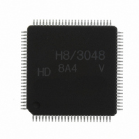
HD64F3048VTF8 Renesas Electronics America, HD64F3048VTF8 Datasheet - Page 24

HD64F3048VTF8
Manufacturer Part Number
HD64F3048VTF8
Description
IC H8 MCU FLASH 128K 100-QFP
Manufacturer
Renesas Electronics America
Series
H8® H8/300Hr
Datasheet
1.HD64F3048F16.pdf
(907 pages)
Specifications of HD64F3048VTF8
Core Processor
H8/300H
Core Size
16-Bit
Speed
8MHz
Connectivity
SCI, SmartCard
Peripherals
DMA, PWM, WDT
Number Of I /o
70
Program Memory Size
128KB (128K x 8)
Program Memory Type
FLASH
Ram Size
4K x 8
Voltage - Supply (vcc/vdd)
2.7 V ~ 5.5 V
Data Converters
A/D 8x10b; D/A 2x8b
Oscillator Type
Internal
Operating Temperature
-20°C ~ 75°C
Package / Case
100-TQFP, 100-VQFP
Lead Free Status / RoHS Status
Contains lead / RoHS non-compliant
Eeprom Size
-
Other names
HD64F3048VX8
- Current page: 24 of 907
- Download datasheet (6Mb)
19.6 Flash Memory Emulation by RAM................................................................................... 629
19.7 Flash Memory PROM Mode............................................................................................. 631
19.8 Flash Memory Programming and Erasing Precautions (Dual-Power Supply) .................. 643
19.9 Notes when Converting the F-ZTAT (Dual-Power Supply) Application Software
Section 20 Clock Pulse Generator
20.1 Overview........................................................................................................................... 653
20.2 Oscillator Circuit............................................................................................................... 655
20.3 Duty Adjustment Circuit................................................................................................... 659
20.4 Prescalers .......................................................................................................................... 659
20.5 Frequency Divider ............................................................................................................ 660
Section 21 Power-Down State
21.1 Overview........................................................................................................................... 663
21.2 Register Configuration...................................................................................................... 665
21.3 Sleep Mode ....................................................................................................................... 669
21.4 Software Standby Mode.................................................................................................... 669
21.5 Hardware Standby Mode .................................................................................................. 673
Rev. 7.00 Sep 21, 2005 page xxii of xxiv
19.5.8 Protect Modes ...................................................................................................... 625
19.5.9 NMI Input Masking ............................................................................................. 628
19.7.1 PROM Mode Setting............................................................................................ 631
19.7.2 Socket Adapter and Memory Map ....................................................................... 632
19.7.3 Operation in PROM Mode................................................................................... 634
to the Mask-ROM Versions .............................................................................................. 651
20.1.1 Block Diagram..................................................................................................... 654
20.2.1 Connecting a Crystal Resonator........................................................................... 655
20.2.2 External Clock Input ............................................................................................ 657
20.5.1 Register Configuration......................................................................................... 660
20.5.2 Division Control Register (DIVCR) .................................................................... 660
20.5.3 Usage Notes ......................................................................................................... 661
21.2.1 System Control Register (SYSCR) ...................................................................... 665
21.2.2 Module Standby Control Register (MSTCR) ...................................................... 667
21.3.1 Transition to Sleep Mode..................................................................................... 669
21.3.2 Exit from Sleep Mode.......................................................................................... 669
21.4.1 Transition to Software Standby Mode ................................................................. 669
21.4.2 Exit from Software Standby Mode ...................................................................... 670
21.4.3 Selection of Waiting Time for Exit from Software Standby Mode...................... 670
21.4.4 Sample Application of Software Standby Mode.................................................. 672
21.4.5 Note...................................................................................................................... 672
21.5.1 Transition to Hardware Standby Mode ................................................................ 673
......................................................................................... 663
.................................................................................. 653
Related parts for HD64F3048VTF8
Image
Part Number
Description
Manufacturer
Datasheet
Request
R

Part Number:
Description:
KIT STARTER FOR M16C/29
Manufacturer:
Renesas Electronics America
Datasheet:

Part Number:
Description:
KIT STARTER FOR R8C/2D
Manufacturer:
Renesas Electronics America
Datasheet:

Part Number:
Description:
R0K33062P STARTER KIT
Manufacturer:
Renesas Electronics America
Datasheet:

Part Number:
Description:
KIT STARTER FOR R8C/23 E8A
Manufacturer:
Renesas Electronics America
Datasheet:

Part Number:
Description:
KIT STARTER FOR R8C/25
Manufacturer:
Renesas Electronics America
Datasheet:

Part Number:
Description:
KIT STARTER H8S2456 SHARPE DSPLY
Manufacturer:
Renesas Electronics America
Datasheet:

Part Number:
Description:
KIT STARTER FOR R8C38C
Manufacturer:
Renesas Electronics America
Datasheet:

Part Number:
Description:
KIT STARTER FOR R8C35C
Manufacturer:
Renesas Electronics America
Datasheet:

Part Number:
Description:
KIT STARTER FOR R8CL3AC+LCD APPS
Manufacturer:
Renesas Electronics America
Datasheet:

Part Number:
Description:
KIT STARTER FOR RX610
Manufacturer:
Renesas Electronics America
Datasheet:

Part Number:
Description:
KIT STARTER FOR R32C/118
Manufacturer:
Renesas Electronics America
Datasheet:

Part Number:
Description:
KIT DEV RSK-R8C/26-29
Manufacturer:
Renesas Electronics America
Datasheet:

Part Number:
Description:
KIT STARTER FOR SH7124
Manufacturer:
Renesas Electronics America
Datasheet:

Part Number:
Description:
KIT STARTER FOR H8SX/1622
Manufacturer:
Renesas Electronics America
Datasheet:


