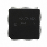
HD64F3048VTF8 Renesas Electronics America, HD64F3048VTF8 Datasheet - Page 73

HD64F3048VTF8
Manufacturer Part Number
HD64F3048VTF8
Description
IC H8 MCU FLASH 128K 100-QFP
Manufacturer
Renesas Electronics America
Series
H8® H8/300Hr
Datasheet
1.HD64F3048F16.pdf
(907 pages)
Specifications of HD64F3048VTF8
Core Processor
H8/300H
Core Size
16-Bit
Speed
8MHz
Connectivity
SCI, SmartCard
Peripherals
DMA, PWM, WDT
Number Of I /o
70
Program Memory Size
128KB (128K x 8)
Program Memory Type
FLASH
Ram Size
4K x 8
Voltage - Supply (vcc/vdd)
2.7 V ~ 5.5 V
Data Converters
A/D 8x10b; D/A 2x8b
Oscillator Type
Internal
Operating Temperature
-20°C ~ 75°C
Package / Case
100-TQFP, 100-VQFP
Lead Free Status / RoHS Status
Contains lead / RoHS non-compliant
Eeprom Size
-
Other names
HD64F3048VX8
- Current page: 73 of 907
- Download datasheet (6Mb)
Table 2.10 Block Transfer Instruction
Instruction
EEPMOV.B
EEPMOV.W
2.6.4
The H8/300H instructions consist of 2-byte (1-word) units. An instruction consists of an operation
field (OP field), a register field (r field), an effective address extension (EA field), and a condition
field (cc).
Operation Field: Indicates the function of the instruction, the addressing mode, and the operation
to be carried out on the operand. The operation field always includes the first 4 bits of the
instruction. Some instructions have two operation fields.
Register Field: Specifies a general register. Address registers are specified by 3 bits, data registers
by 3 bits or 4 bits. Some instructions have two register fields. Some have no register field.
Effective Address Extension: Eight, 16, or 32 bits specifying immediate data, an absolute
address, or a displacement. A 24-bit address or displacement is treated as 32-bit data in which the
first 8 bits are 0 (H'00).
Condition Field: Specifies the branching condition of Bcc instructions.
Basic Instruction Formats
Size
—
—
Function
if R4L
else next;
if R4
else next;
Transfers a data block according to parameters set in general
registers R4L or R4, ER5, and ER6.
R4L or R4: Size of block (bytes)
ER5:
ER6:
Execution of the next instruction begins as soon as the transfer is
completed.
0 then
0 then
repeat
until
repeat
until
Starting source address
Starting destination address
@ER5+
R4L = 0
@ER5+
R4 = 0
Rev. 7.00 Sep 21, 2005 page 47 of 878
@ER6+, R4L – 1
@ER6+, R4 – 1
R4
REJ09B0259-0700
R4L
Section 2 CPU
Related parts for HD64F3048VTF8
Image
Part Number
Description
Manufacturer
Datasheet
Request
R

Part Number:
Description:
KIT STARTER FOR M16C/29
Manufacturer:
Renesas Electronics America
Datasheet:

Part Number:
Description:
KIT STARTER FOR R8C/2D
Manufacturer:
Renesas Electronics America
Datasheet:

Part Number:
Description:
R0K33062P STARTER KIT
Manufacturer:
Renesas Electronics America
Datasheet:

Part Number:
Description:
KIT STARTER FOR R8C/23 E8A
Manufacturer:
Renesas Electronics America
Datasheet:

Part Number:
Description:
KIT STARTER FOR R8C/25
Manufacturer:
Renesas Electronics America
Datasheet:

Part Number:
Description:
KIT STARTER H8S2456 SHARPE DSPLY
Manufacturer:
Renesas Electronics America
Datasheet:

Part Number:
Description:
KIT STARTER FOR R8C38C
Manufacturer:
Renesas Electronics America
Datasheet:

Part Number:
Description:
KIT STARTER FOR R8C35C
Manufacturer:
Renesas Electronics America
Datasheet:

Part Number:
Description:
KIT STARTER FOR R8CL3AC+LCD APPS
Manufacturer:
Renesas Electronics America
Datasheet:

Part Number:
Description:
KIT STARTER FOR RX610
Manufacturer:
Renesas Electronics America
Datasheet:

Part Number:
Description:
KIT STARTER FOR R32C/118
Manufacturer:
Renesas Electronics America
Datasheet:

Part Number:
Description:
KIT DEV RSK-R8C/26-29
Manufacturer:
Renesas Electronics America
Datasheet:

Part Number:
Description:
KIT STARTER FOR SH7124
Manufacturer:
Renesas Electronics America
Datasheet:

Part Number:
Description:
KIT STARTER FOR H8SX/1622
Manufacturer:
Renesas Electronics America
Datasheet:


