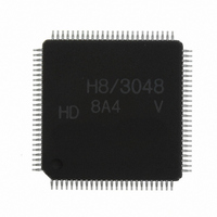
HD64F3048VTF8 Renesas Electronics America, HD64F3048VTF8 Datasheet - Page 545

HD64F3048VTF8
Manufacturer Part Number
HD64F3048VTF8
Description
IC H8 MCU FLASH 128K 100-QFP
Manufacturer
Renesas Electronics America
Series
H8® H8/300Hr
Datasheet
1.HD64F3048F16.pdf
(907 pages)
Specifications of HD64F3048VTF8
Core Processor
H8/300H
Core Size
16-Bit
Speed
8MHz
Connectivity
SCI, SmartCard
Peripherals
DMA, PWM, WDT
Number Of I /o
70
Program Memory Size
128KB (128K x 8)
Program Memory Type
FLASH
Ram Size
4K x 8
Voltage - Supply (vcc/vdd)
2.7 V ~ 5.5 V
Data Converters
A/D 8x10b; D/A 2x8b
Oscillator Type
Internal
Operating Temperature
-20°C ~ 75°C
Package / Case
100-TQFP, 100-VQFP
Lead Free Status / RoHS Status
Contains lead / RoHS non-compliant
Eeprom Size
-
Other names
HD64F3048VX8
- Current page: 545 of 907
- Download datasheet (6Mb)
14.3.3
Figure 14.3 shows the data format of the smart card interface. In receive mode, parity is checked
once per frame. If a parity error is detected, an error signal is returned to the transmitting device to
request retransmission. In transmit mode, the error signal is sampled and the same data is
retransmitted if the error signal is low.
The operating sequence is as follows.
1. When not in use, the data line is in the high-impedance state, and is pulled up to the high level
2. To start transmitting a frame of data, the transmitting device transmits a low start bit (Ds),
3. Next, in the smart card interface, the transmitting device returns the data line to the high-
4. The receiving device performs a parity check. If there is no parity error, the receiving device
5. If the transmitting device does not receive an error signal, it proceeds to transmit the next data.
through a resistor.
followed by eight data bits (D0 to D7) and a parity bit (Dp).
impedance state. The data line is pulled up to the high level through a resistor.
waits to receive the next data. If a parity error is present, the receiving device outputs a low
error signal (DE) to request retransmission of the data. After outputting the error signal for a
designated interval, the receiving device returns the signal line to the high-impedance state.
The signal line is pulled back up to the high level through the pull-up resistor.
If it receives an error signal, it returns to step 2 and transmits the same data again.
Data Format
No parity error
Parity error
Ds:
D0 to D7:
Dp:
DE:
Ds
Ds
Start bit
Data bits
Parity bit
Error signal
D0
D0
Figure 14.3 Smart Card Interface Data Format
D1
D1
Output from transmitting device
Output from transmitting device
D2
D2
D3
D3
D4
D4
D5
D5
D6
D6
Rev. 7.00 Sep 21, 2005 page 519 of 878
D7
D7
Section 14 Smart Card Interface
Dp
Dp
Output from
receiving device
DE
REJ09B0259-0700
Related parts for HD64F3048VTF8
Image
Part Number
Description
Manufacturer
Datasheet
Request
R

Part Number:
Description:
KIT STARTER FOR M16C/29
Manufacturer:
Renesas Electronics America
Datasheet:

Part Number:
Description:
KIT STARTER FOR R8C/2D
Manufacturer:
Renesas Electronics America
Datasheet:

Part Number:
Description:
R0K33062P STARTER KIT
Manufacturer:
Renesas Electronics America
Datasheet:

Part Number:
Description:
KIT STARTER FOR R8C/23 E8A
Manufacturer:
Renesas Electronics America
Datasheet:

Part Number:
Description:
KIT STARTER FOR R8C/25
Manufacturer:
Renesas Electronics America
Datasheet:

Part Number:
Description:
KIT STARTER H8S2456 SHARPE DSPLY
Manufacturer:
Renesas Electronics America
Datasheet:

Part Number:
Description:
KIT STARTER FOR R8C38C
Manufacturer:
Renesas Electronics America
Datasheet:

Part Number:
Description:
KIT STARTER FOR R8C35C
Manufacturer:
Renesas Electronics America
Datasheet:

Part Number:
Description:
KIT STARTER FOR R8CL3AC+LCD APPS
Manufacturer:
Renesas Electronics America
Datasheet:

Part Number:
Description:
KIT STARTER FOR RX610
Manufacturer:
Renesas Electronics America
Datasheet:

Part Number:
Description:
KIT STARTER FOR R32C/118
Manufacturer:
Renesas Electronics America
Datasheet:

Part Number:
Description:
KIT DEV RSK-R8C/26-29
Manufacturer:
Renesas Electronics America
Datasheet:

Part Number:
Description:
KIT STARTER FOR SH7124
Manufacturer:
Renesas Electronics America
Datasheet:

Part Number:
Description:
KIT STARTER FOR H8SX/1622
Manufacturer:
Renesas Electronics America
Datasheet:


