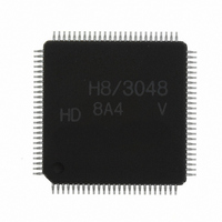
HD64F3048VTF8 Renesas Electronics America, HD64F3048VTF8 Datasheet - Page 669

HD64F3048VTF8
Manufacturer Part Number
HD64F3048VTF8
Description
IC H8 MCU FLASH 128K 100-QFP
Manufacturer
Renesas Electronics America
Series
H8® H8/300Hr
Datasheet
1.HD64F3048F16.pdf
(907 pages)
Specifications of HD64F3048VTF8
Core Processor
H8/300H
Core Size
16-Bit
Speed
8MHz
Connectivity
SCI, SmartCard
Peripherals
DMA, PWM, WDT
Number Of I /o
70
Program Memory Size
128KB (128K x 8)
Program Memory Type
FLASH
Ram Size
4K x 8
Voltage - Supply (vcc/vdd)
2.7 V ~ 5.5 V
Data Converters
A/D 8x10b; D/A 2x8b
Oscillator Type
Internal
Operating Temperature
-20°C ~ 75°C
Package / Case
100-TQFP, 100-VQFP
Lead Free Status / RoHS Status
Contains lead / RoHS non-compliant
Eeprom Size
-
Other names
HD64F3048VX8
- Current page: 669 of 907
- Download datasheet (6Mb)
19.8
(1) Program with the specified voltages and timing.
The rated programming voltage (V
If the PROM programmer is set to Renesas Technology HN28F101 specifications, V
12.0 V. Applied voltages in excess of the rating can permanently damage the device. Insure, in
particular, that peak overshoot at the Vpp and MD2 pins does not exceed the maximum rating of
13 V. Also, be very careful about PROM programmer overshoot.
(2) Before programming, check that the chip is correctly mounted in the PROM
programmer. Overcurrent damage to the device can result if the index marks on the PROM
programmer socket, socket adapter, and chip are not correctly aligned.
(3) Don’t touch the socket adapter or chip while programming. Touching either of these can
cause contact faults and write errors.
(4) Precautions in turning the programming voltage (V
19.24):
Apply the programming voltage (V
stable condition. Shut off V
condition. If V
to 5.5 V), since microcontroller operation is unstable and flash memory protection is not
functioning, the flash memory may be programmed or erased by mistake. This can occur even
if V
its rated voltage range (V
oscillator has stopped (except in standby), or if a program runaway has occurred. After V
power-up, do not apply V
and the microcontroller is safely in the reset state, or the reset has been cleared.
These power-on and power-off timing requirements should also be satisfied in the event of a
power failure and recovery from a power failure. If these requirements are not satisfied, the
flash memory may not only be unintentionally programmed or erased; it may be permanently
damaged.
The V
in FLMCR is set or cleared while a voltage of 12.0 ± 0.6 V is being applied to the V
After the V
EBR2) and the EV, PV, E, and P bits in FLMCR. Accordingly, program or erase flash memory
CC
PP
Flash Memory Programming and Erasing Precautions (Dual-Power
Supply)
= 0 V. The same danger of incorrect programming or erasing exists when V
bit in the flash memory control register (FLMCR) is set or cleared when the V
PP
E bit is set, it becomes possible to write the erase block registers (EBR1 and
PP
is turned on or off while V
Section 19 Flash Memory (H8/3048F: Dual Power Supply (V
CC
PP
PP
= 2.7 to 5.5 V) if the clock oscillator has not stabilized, if the clock
until the clock oscillator has had time to settle (t
before V
PP
) of the flash memory is 12.0 V.
PP
) after the rise of V
CC
, again while the microcontroller is in a stable
CC
is not within its rated voltage range (V
Rev. 7.00 Sep 21, 2005 page 643 of 878
PP
CC
) on and off (see figures 19.22 to
, when the microcontroller is in a
OSC1
REJ09B0259-0700
= 20 ms min)
PP
CC
will be
PP
PP
CC
is within
pin.
PP
= 12 V))
= 2.7
E bit
CC
Related parts for HD64F3048VTF8
Image
Part Number
Description
Manufacturer
Datasheet
Request
R

Part Number:
Description:
KIT STARTER FOR M16C/29
Manufacturer:
Renesas Electronics America
Datasheet:

Part Number:
Description:
KIT STARTER FOR R8C/2D
Manufacturer:
Renesas Electronics America
Datasheet:

Part Number:
Description:
R0K33062P STARTER KIT
Manufacturer:
Renesas Electronics America
Datasheet:

Part Number:
Description:
KIT STARTER FOR R8C/23 E8A
Manufacturer:
Renesas Electronics America
Datasheet:

Part Number:
Description:
KIT STARTER FOR R8C/25
Manufacturer:
Renesas Electronics America
Datasheet:

Part Number:
Description:
KIT STARTER H8S2456 SHARPE DSPLY
Manufacturer:
Renesas Electronics America
Datasheet:

Part Number:
Description:
KIT STARTER FOR R8C38C
Manufacturer:
Renesas Electronics America
Datasheet:

Part Number:
Description:
KIT STARTER FOR R8C35C
Manufacturer:
Renesas Electronics America
Datasheet:

Part Number:
Description:
KIT STARTER FOR R8CL3AC+LCD APPS
Manufacturer:
Renesas Electronics America
Datasheet:

Part Number:
Description:
KIT STARTER FOR RX610
Manufacturer:
Renesas Electronics America
Datasheet:

Part Number:
Description:
KIT STARTER FOR R32C/118
Manufacturer:
Renesas Electronics America
Datasheet:

Part Number:
Description:
KIT DEV RSK-R8C/26-29
Manufacturer:
Renesas Electronics America
Datasheet:

Part Number:
Description:
KIT STARTER FOR SH7124
Manufacturer:
Renesas Electronics America
Datasheet:

Part Number:
Description:
KIT STARTER FOR H8SX/1622
Manufacturer:
Renesas Electronics America
Datasheet:


